
By John “Buddy” Showalter, PE, and Sandra Hyde, PE
Click here to view the article with images in the digital flipbook.
This multi-part series discusses significant structural changes to the 2024 International Building Code (IBC) by the International Code Council (ICC). This article includes an overview of changes to IBC Chapter 23 on wood. Only a portion of the chapter’s total number of code changes is discussed in this article. More information on the code changes can be found in the 2024 Significant Changes to the International Building Code available from ICC.
Referenced Standards
Table 1 provides a list of standards that are newly referenced or updated in the 2024 IBC.
Wood Structural Panel Wall Sheathing
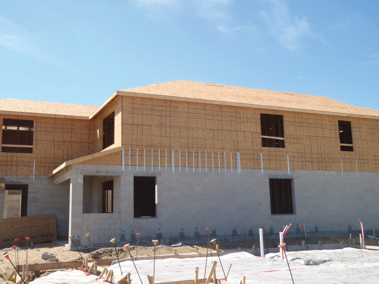
IBC Table 2304.6.1 provides requirements and limitations for wood structural panels (WSP) used as exterior wall sheathing when resisting wind pressure (Figure 1). For a given wind speed and exposure category, the table gives the minimum nail size, WSP span rating, panel thickness, stud spacing, and nailing schedule. The limitations of the table are that the building must be enclosed, the mean roof height must be not greater than 30 feet, and the topographic factor must be equal to 1.0.
Change Significance: Tabulated values are modified for basic wind speeds to be consistent with ASCE 7-22 Minimum Design Loads and Associated Criteria for Buildings and Other Structures. This change updates the tabulated values from allowable stress design wind speeds (Vasd) to basic wind speeds (V) for consistency with ASCE 7-22. When developing these modifications, stud and panel capacities, nail withdrawal resistance, and nail-head pull-through capacities were evaluated in the same manner as the previous table, resulting in comparable design requirements as the wind speeds are soft-converted from Vasd values per IBC Section 1609.3.1. The tabulated wind speeds are also consistent with those in 2021 International Residential Code (IRC) Table R602.3(3).
Footnote “b” was updated to reference ASCE 7 Section 30.4. Since the revised table reflects basic wind speeds, the previous text in footnote “d” is no longer required but is replaced by a new note. The new footnote “d” text recognizes the minimum specific gravity basis of 0.42 for the WSP fastener spacing and provides a prescriptive option (i.e., multiply spacing by 0.67) for framing species with lower specific gravity down to a specific gravity equal to 0.35. Engineered design of the WSP fasteners is required when the specific gravity is less than 0.35 for the lumber species used for wall framing.
Fire Protection of Connections
IBC Section 2304.10.1 provides two options for demonstrating compliance for the protection of connections in Types IV-A, IV-B, and IV-C construction: a testing option and a calculation option. The provisions do not apply to connections in heavy timber (IV-HT) construction, because heavy timber structural members do not have a prescribed fire-resistance rating. Connections in Type IV-A, IV-B and IV-C construction are required to have fire protection for the time associated with fire protection of the primary structural frame members (Figure 2).
2304.10.1 Connection fire-resistance rating Fire protection of connections. Fire-resistance ratings for connections in Connections used with fire-resistance-rated members and in fire-resistance-rated assemblies of Type IV-A, IV-B or IV-C construction shall be protected for the time associated with the fire-resistance rating. Protection time shall be determined by one of the following:
1. Testing in accordance with Section 703.2 where the connection is part of the fire-resistance test.
2. Engineering analysis that demonstrates that the temperature rise at any portion of the connection is limited to an average temperature rise of 250°F (139°C), and a maximum temperature rise of 325°F (181°C), for a time corresponding to the required fire-resistance rating of the structural element being connected. For the purposes of this analysis, the connection includes connectors, fasteners and portions of wood members included in the structural design of the connection.
Change Significance: This change clarifies the code intent that connections are required to be protected for the time associated with the fire-resistance rating of members and assemblies as required by IBC Sections 704.2 for the primary structural frame.
However, IBC Section 704.2 does not require connections that join elements of the structural frame to be tested per ASTM E119 Standard Test Methods for Fire Tests of Building Construction and Materials or UL263 Fire Tests of Building Construction and Materials. The connections must only be protected with a material having the fire-resistance rating required for the structural members that they connect. It is neither practical nor possible to test connections in a standard fire test furnace since there is no capability to test large connections used to transfer gravity loads. In addition, neither ASTM E119 nor UL263 includes any provisions on how to test connections and assess their performance.
See the May 2023 issue of STRUCTURE for more background on design for fire protection of mass timber connections.
Wood Shear Walls and Diaphragms
IBC Section 2305.1 references AWC’s Special Design Provisions for Wind and Seismic (SDPWS) for the design and construction of wood shear walls and wood diaphragms to resist wind, seismic, or other lateral loads.
2305.1 General. Structures using wood-frame shear walls or wood-frame diaphragms to resist wind, or seismic or other lateral loads shall be designed and constructed in accordance with AWC SDPWS and the applicable provisions of Sections 2305, 2306 and 2307.
2305.1.2 Permanent load duration. Permanent loads are associated with permanent load duration in accordance with the ANSI/AWC NDS. For wood shear walls and wood diaphragms designed to resist lateral loads of permanent load duration only and that are not in combination with wind or seismic lateral loads, the design unit shear capacities shall be taken as the AWC SDPWS nominal unit shear capacities, multiplied by 0.2 for use with allowable stress design in Section 2306 and 0.3 for use with load and resistance factor design in Section 2307.
Change Significance: Terminology in IBC Section 2305.1 changes to use “wood shear walls” and “wood diaphragms” instead of “wood-frame” shear walls and diaphragms. The terminology change is driven by the need to cover the design of both wood-frame and cross-laminated timber shear walls and diaphragms in the SDPWS (Figure 3).
Reference to the SDPWS is appropriate for the design of wood shear walls and diaphragms to resist wind and seismic loads, but for resistance to permanent lateral loads, such as soil loads in foundation design, the nominal unit shear capacities in SDPWS need further reduction to account for long-term effects. Permanent loads are associated with a permanent load duration factor (allowable stress design, ASD) or time-effect factor (load and resistance factor design, LRFD) as defined by the NDS. IBC Section 2305.1.2 now requires the use of a 0.2 factor for ASD and a 0.3 factor for LFRD.
Hillside Light-frame Wood Construction
One of the most important aspects of prescriptive methods is meeting the restrictions and limitations required to use the method. The structures for which conventional light-frame wood construction is applicable are described in IBC Section 2308.2. For light-frame wood dwellings on steep hillsides, the typical assumption of floor loads transferring to braced wall panels based on the tributary area of a flexible wood floor may not provide adequate seismic performance (Figure 4). This building configuration was found to be vulnerable in the 1994 Northridge, California earthquake. Whether the earthquake motion occurs across the slope or perpendicular to the hill, seismic forces follow the stiffest load path to the uphill foundation, rather than distributing evenly to all braced wall panels as assumed in prescriptive IBC seismic wall bracing provisions.
CHAPTER 2
DEFINITIONS
CRIPPLE WALL CLEAR HEIGHT. The vertical height of a cripple wall from the top of the foundation to the underside of floor framing above.
2308.2 Limitations. Buildings are permitted to be constructed in accordance with the provisions of conventional light-frame construction, subject to the limitations in Sections 2308.2.1 through 2308.2.6 2308.2.7.
(No changes to Sections 2308.2.1, 2308.2.2, 2308.2.4 and 2308.2.5. Changes to 2308.2.3 and 2308.2.6 not shown for brevity.)
2308.2.7 Hillside light-frame construction. Design in accordance with Section 2308.3 shall be provided for the floor immediately above the cripple walls or post and beam systems and all structural elements and connections from this floor down to and including connections to the foundation and design of the foundation to transfer lateral loads from the framing above in buildings where all of the following apply:
1. The grade slope exceeds 1 unit vertical in 5 units horizontal where averaged across the full length of any side of the building.
2. The tallest cripple wall clear height exceeds 7 feet (2134 mm); or, where a post and beam system occurs at the building perimeter, the post and beam system tallest post clear height exceeds 7 feet (2134 m).
3. Of the total plan area below the lowest framed floor, whether open or enclosed, less than 50 percent is occupiable space having interior wall finishes conforming to Section 2304.7 or Chapter 25.
Exception: Light-frame buildings in which the lowest framed floor is supported directly on concrete or masonry walls over the full length of all sides except the downhill side of the building are exempt from this provision.
Change Significance: These new load path provisions provide a correlation between the prescriptive requirements of IBC Section 2308 and IRC Section R301.2.2.6 Item 8. The hillside requirement was added to the 2021 IRC with the intent of improving the seismic performance of hillside light-frame wood buildings. A related modification was also made to ASCE 7-22 to provide additional guidance to engineers designing these types of structures.
Wind Uplift
Wind loads (based on main wind force-resisting system pressures) can cause considerable uplift forces on roof framing. The uplift loads must be positively transferred into the structure below to resist the uplift (Figure 5).
2308.11.4 Wind uplift. The roof construction shall have rafter and truss ties to the wall below. Resultant uplift loads shall be transferred to the foundation using a continuous load path. The rafter or truss-to-wall connection shall comply with Tables 2304.10.2 and 2308.11.4.
Exception: The truss-to-wall connection shall be determined from the uplift forces as specified on the truss design drawings or as shown on the construction documents.
Change Significance: Changes to IBC Section 2308.11.4 (formerly 2308.7.5) and the corresponding table update roof-to-wall connection uplift loads to comply with the IBC-referenced standard ASCE 7-22. Tabulated wind uplift loads have been updated based on the basic wind speeds used in ASCE 7-22 (and ASCE 7-16) which match the required basic wind speeds of IBC Figures 1609.3(1) through 1609.3(4). (see the March 2024 issue of STRUCTURE on IBC Chapter 16 loads for more background).
Basic wind speeds are tabulated for 90-140 mph which provides values up to the maximum wind speed permitted in IBC Section 2308.2.4 for conventional light-frame construction. Uplift loads for Exposures C and D with an assumed mean roof height (MRH) of 33 feet are also now tabulated eliminating the need for the table in Footnote “a”. A higher MRH will require engineering analysis for uplift connectors.
Uplift connection requirements now include the effects of 24-inch overhangs. Calculations are no longer required to determine the magnitude of the uplift loads by adding the overhang loads previously found in the table. While conservative, engineering analysis can be used to reduce uplift loads for roofs with shorter overhangs. Overhangs greater than 24 inches will require engineering analysis.
A new exception is added to IBC Section 2308.11.4 to allow truss-to-wall connections to be designed using either the loads on the truss design drawings or the construction documents. This new language is meant to be consistent with IRC Section R802.11.1 for truss uplift resistance.
Conclusion
Structural engineers should be aware of significant structural changes in the 2024 IBC Chapter 23 on wood. Tabulated values are modified for basic wind speeds to be consistent with ASCE 7-22. New footnote text provides a prescriptive option for framing species with a specific gravity lower than 0.42. Connections in Type IV-A, IV-B and IV-C construction are required to have fire protection for the time associated with fire protection of the primary structural frame. Design requirements for wood-frame and cross-laminated timber shear walls and diaphragms are added. For resistance to permanent lateral loads, such as soil loads in foundation design, capacity reductions are added to account for long-term effects in nominal unit shear capacities. New load path requirements are intended to improve the seismic performance of hillside light-frame wood buildings. Roof-to-wall connection uplift loads are updated to be consistent with ASCE 7-22. ■
About the Author
John “Buddy” Showalter, PE, M. ASCE, M. NCSEA (bshowalter@iccsafe.org) is a Senior Staff Engineer and Sandra Hyde, PE, M. ASCE, M. NCSEA (shyde@iccsafe.org) is Managing Director of ICC’s Consulting Group.