
Unintended Consequences
Many brick-clad buildings constructed from the 1950s through the 1970s employ an early version of cavity wall construction that looks like contemporary veneer wall construction from the outside but has different structural behavior. Repairs and modifications to such cavity walls that are seemingly cosmetic or undertaken to improve envelope performance can change the wall’s load path and impact its ability to resist lateral loads. Owners, contractors, and design professionals should be able to recognize cavity wall construction, understand when potential repairs or modifications warrant structural evaluation, and design and implement structural strengthening when required.
Construction and Structural Behavior
Original Design and Construction
Early cavity walls, as defined in this article, comprise an unreinforced concrete masonry (CMU) interior wythe (commonly 4 in. thick, and sometimes 6 in. or 8 in. thick), an air gap, and a brick masonry exterior wythe (Figure 1). The two wythes are tied with horizontal wire reinforcement embedded in the masonry bed joints. Early cavity walls typically were designed using empirical span-to-thickness ratio requirements that considered a combination of the brick thickness and the CMU thickness, prescribed minimum masonry material properties, and prescribed the gage and spacing of the wire reinforcement that joined the wythes.
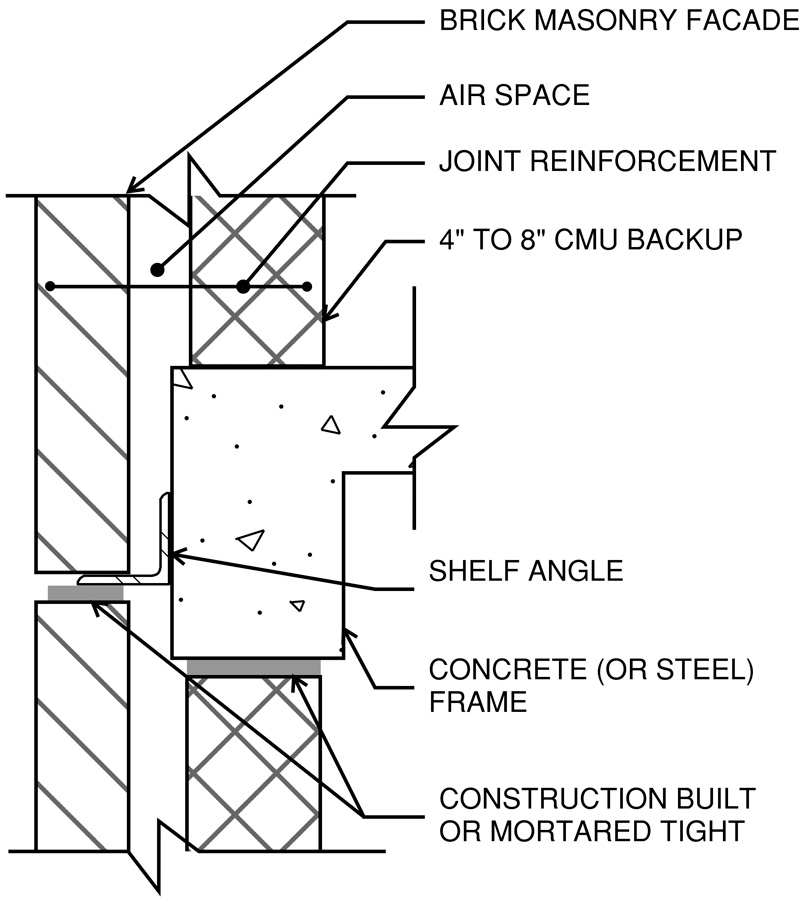
Early cavity walls were often constructed with brick relieving angles at every story; however, horizontal expansion joints below the angles were typically narrow, if they existed at all. While architectural standards at the time called for narrow open joints below the relieving angles, brick masonry was often installed directly in contact with the angle or with mortar in the joint. Connections of the CMU wythe to the building frame were designed to include reinforcing dowels, dovetail anchor assemblies, or simply mortared bed joints, though in practice, such connections were sometimes omitted entirely during construction. If any connections of brick wythes to the building structure were provided, they usually consisted of mortar joints to relieving angles at each floor.
Early cavity walls generally lack continuous air, water, vapor, and thermal barriers. The limited enclosure elements that are incorporated primarily consider only water management within the wall cavity and commonly include elements such as through-wall flashings and weeps at brick relieving angles and window heads.
Structural Behavior
Unlike modern brick veneer construction, in which the brick is typically idealized as purely a cladding element that transfers all lateral forces to a lateral-load-resisting backup wall, the brick and CMU wythes of cavity wall construction resist out-of-plane lateral loads as a combined assembly. The embedded horizontal joint reinforcement ties the brick and CMU wythes to each other and distributes load between them but is not typically stiff enough to create fully composite flexural behavior of the wall assembly, the proportion of lateral load resisted by each wythe depends on its relative stiffness. At the ends of the wall span, early cavity walls were intended to transfer shear to the base building frame through the CMU wythe, but the actual load path varies depending on each wythe’s method of attachment to the building.
Common Problems and Repairs
Cavity walls subject to exposure-related deterioration may exhibit conditions that require more than simply in-kind mortar joint repointing and localized brick repair or replacement. Three commonly encountered conditions include brick masonry distress caused by restraint of volume change; corrosion of embedded horizontal joint reinforcement; and inadequate envelope performance given modern expectations.
Distress Caused by Restraint of Volume Change
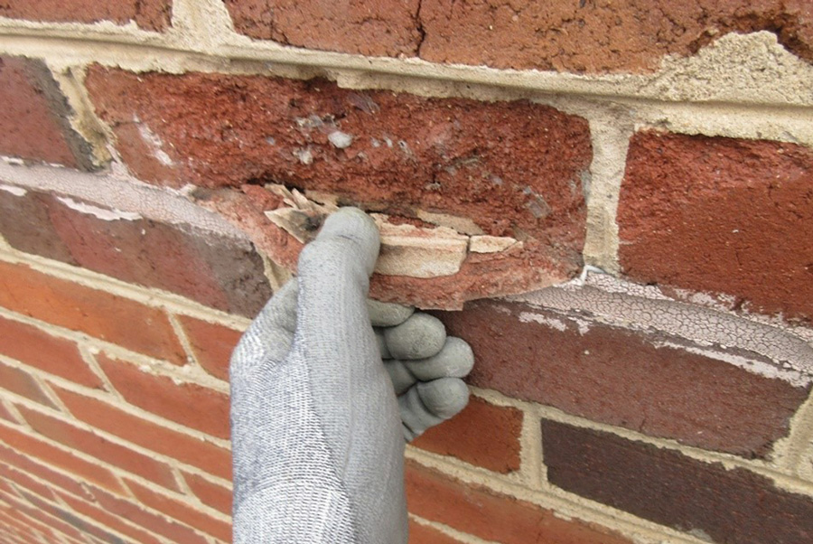
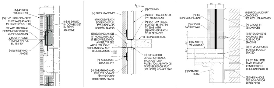
Symptoms of restraint-induced stresses that may trigger an evaluation include cracks, spalls, and bulges in the exposed brick wythe (Figure 2). Brick is at its driest state immediately after manufacturing and takes on moisture over its lifetime. This absorption results in irreversible brick growth. Brick also changes volume cyclically as it expands and contracts with temperature change. When the brick grows without sufficient horizontal expansion joints to accommodate the growth, the building structure restrains the brick expansion. Early cavity wall systems containing narrow horizontal expansion joints (by design) or no horizontal expansion joints (due to poor construction) are not able to accommodate brick growth. One common repair strategy to reduce the likelihood of worsening distress due to restrained brick expansion is to introduce an expansion joint below relieving angles with sufficient joint width to accommodate the movement (Figure 3).
Corroded Horizontal Joint Reinforcement
Symptoms of corroded horizontal joint reinforcement include cracked or spalled brick mortar joints and corrosion staining on the face of the wall. Corrosion occurs in the presence of moisture and oxygen, and cavity walls that manage water poorly are susceptible to it. Corrosion product (rust) has a larger volume than the original, stable base metal, and the increase in volume induces stresses in the mortar joints that can lead to the cracks and mortar spalls. If allowed to progress long enough, the corrosion can lead to section loss, compromising the integrity of the joint reinforcement. Depending on the extent and severity of corrosion-related deterioration, common repair approaches include localized or widespread brick removal to repair or replace corroded reinforcement.
Envelope Performance Issues
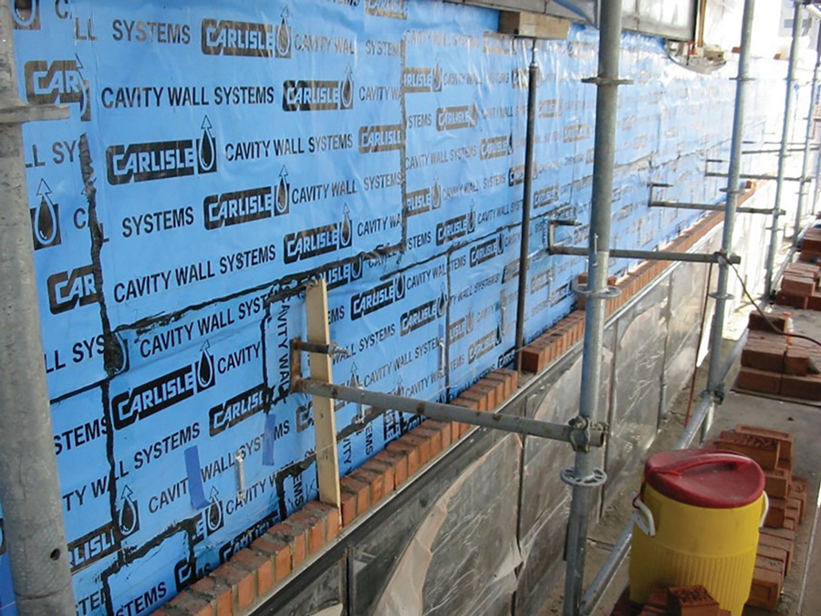
Although often initially spurred by observations of brick distress to assess their building’s exterior walls, once they begin investigating, building owners may become aware of other envelope performance issues associated with cavity wall construction. Common problems include leakage to the interior, ineffective water management within the wall cavity (e.g., water dwells within the cavity), missing or deficient flashings, and occupant comfort issues brought on by lack of an air barrier or poor thermal performance and humidity control.
Leakage and water management issues can sometimes be mitigated through modifications made local to brick relieving angles and windows, which typically require removal and replacement of brick above and/or below the angle or window and installation of new flashing and/or weeps. In other cases the scope may expand to include full removal and replacement of the brick wythe. Examples include when moisture-related deterioration of interior building components advances; more reliable moisture mitigation is desired; or a new air barrier and insulation are desired for improved code compliance, energy efficiency, or occupant comfort. It is impractical, however, to salvage horizontal joint reinforcement and still provide a reliable air/water barrier while implementing such intrusive modifications. Therefore, in these circumstances, the existing joint reinforcement typically is cut at the CMU face and replaced with post-installed brick veneer ties (Figure 4).
Structural Effects of Modifications
Common approaches used to address the restraint-of-volume distress, corroded horizontal joint reinforcement, and envelope performance issues described above can have unintended structural implications. Whether the modifications to the cavity wall are local to relieving angles (e.g., cutting in new horizontal expansion joints) or wholesale in nature (e.g., removing and replacing the entire brick wythe and cutting the joint reinforcement), the designer must review and understand the potential structural consequences of these modifications. Below, two types of modifications are described which can affect the cavity wall’s load path and its structural capacity.
Horizontal Expansion Joints Below Relieving Angles
Adequately sized horizontal expansion joints are important for the long-term durability of masonry walls. However, introducing these joints into walls that previously lacked them alters the load path of the wall. Compressive stresses in the existing brick that develop in the absence of an adequately sized expansion joint reduce the net flexural tension on mortar joints when the wall is subjected to out-of-plane lateral load. Releasing the precompression by introducing a horizontal expansion joint increases the net flexural tensile stress in the wall when it is loaded out of plane. Empirical cavity walls, especially those with horizontal through-cracks or non-compliant span-to-thickness ratios, might rely on this precompression to resist lateral loads.
Precompression also affects the capacity of masonry wall connections to the base building structure by increasing frictional resistance. Releasing the precompression alters the load path through which lateral-load induced shear forces are transmitted to the base building.
Cutting Horizontal Joint Reinforcement
Cutting existing embedded horizontal joint reinforcement at the exterior face of the CMU wythe and replacing it with conventional brick ties to address corroded reinforcement or to accommodate new wall waterproofing, air barrier, and insulation in the cavity makes the existing wall noncompliant with empirical requirements for cavity walls. Post-installed brick ties fastened to the face of the CMU behave differently than joint reinforcement embedded in the CMU wythe, which impacts the load-sharing behavior between the brick and CMU wythes. Therefore, cutting the embedded joint reinforcement alters the original design intent and the in-situ structural behavior of the wall.
Evaluation and Analysis
Building Code Triggers for Structural Evaluation
Most codes used by local jurisdictions (state, county, or city) adopt, in whole or in part, the International Building Code (IBC) and, by reference, the International Existing Building Code (IEBC). The 2018 IEBC includes the following relevant definitions: Repairs are the “reconstruction, replacement or renewal of any part of an existing building for the purpose of its maintenance or to correct damage.” Alterations are “any construction or renovation to an existing structure other than a repair or addition.” Modifications like the introduction of new horizontal expansion joints below relieving angles and the cutting of embedded horizontal joint reinforcement change the structural behavior of the cavity wall and should be classified as “alterations.” For “alterations,” the IEBC requires lateral-load-resisting elements that experience a stress increase of more than 10% due to the alteration to be analyzed for their ability to resist current code loads, and strengthened if needed.
Structural Analysis of Modified Wall
Unless the designer can demonstrate that the modifications to the cavity wall – adding new expansion joints beneath the relieving angles and/or cutting the existing horizontal joint reinforcement – result in a stress increase on each of the wall elements of no more than 10%, they must analyze the modified wall for its ability to resist current code loads.
Unreinforced CMU used in the construction of early cavity walls is typically 8 in. thick or less and frequently lacks positive anchorage to the building structure. Designers should analyze the existing wall assembly in its proposed modified configuration against current code-prescribed lateral loads using estimates of material properties published in standards contemporary to the time of original construction. If the analysis finds that the modified wall is unable to resist current code loads and there is a strong desire to avoid strengthening work, it may be possible to justify higher material properties than those published in contemporary standards with a testing program. However, such a program can itself be costly to design and execute and does not guarantee results that would eliminate or substantially reduce the need for wall strengthening.
Wall Strengthening Approaches
When the proposed modified wall is unable to resist code-prescribed loads as required by IEBC, the following strengthening approaches are available, among others:
Fiber Reinforced Polymer Strips – Install fiber reinforced polymer (FRP) strips to strengthen the existing CMU wythe. FRP will be required on both the interior and exterior faces of the CMU to resist out-of-plane loads in opposing directions. If existing top- and/or bottom-of-wall connections also require strengthening, provide new attachments between the wall and the building structure. Where new attachment details include post-installed fasteners, designers should keep in mind that commonly used fastener design tables and design-assist software are calibrated to modern material properties and workmanship; requiring in-situ tests to demonstrate fastener strengths in existing material substrates is prudent for validating assumed design values.
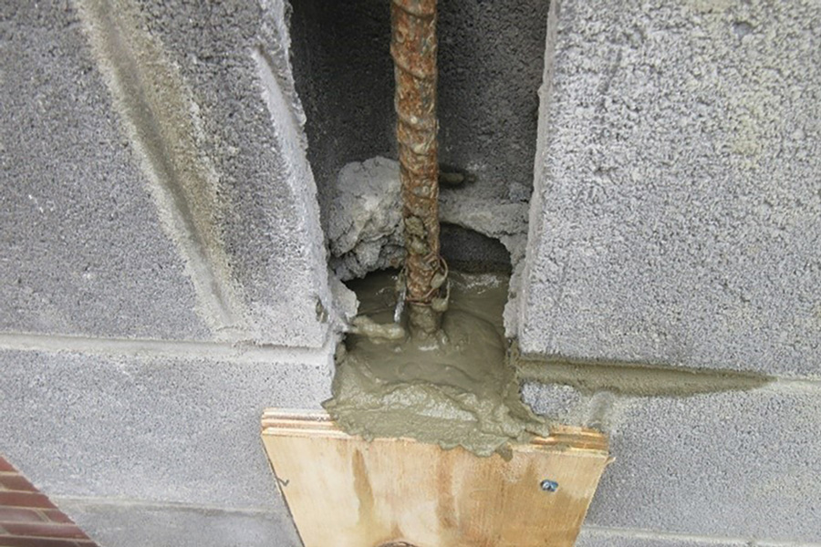
Internal Reinforcing Bars – Reinforce existing CMU by cutting cells open, installing vertical reinforcing bars, and grouting newly reinforced cells solid (Figure 5). Work can be performed from either the interior or exterior of the building. New reinforcing bars may connect directly to the base building structure, or separate top- and/or bottom-of-wall attachments may be added where needed, as described in the FRP strengthening approach above.
Cold Formed Metal Framed Backup Wall – Install a new interior cold formed metal framed (CFMF) backup wall to strengthen or entirely bypass the existing cavity wall. The supplemental wall must be sufficiently stiff relative to the cavity wall and adequately connected to the existing CMU to receive out-of-plane lateral loads. Designing the CFMF wall with at least an L/600 deflection limit will limit masonry cracking as out-of-plane loads transfer between the walls. The new backup wall can be attached at its top and bottom to the existing building structure similarly to modern backup walls in veneer wall assemblies. In this approach, the new wall installed against the interior face of the CMU will reduce the occupiable floor space somewhat, but the end result is a functionally new backup wall that can be constructed using methods familiar to most contractors.
Wall Replacement or Overcladding – If a strengthening approach is not preferred, the existing cavity wall can be demolished and replaced with a new exterior wall assembly, or it can be abandoned in place behind a new overclad wall. Both approaches offer the opportunity for the owner and design team to fully re-envision the exterior wall from an aesthetic and envelope performance perspective, if desired, but they require a comprehensive review of the existing building structure and foundations for their ability to support the new exterior wall.
The relative merits of the various strengthening and replacement strategies will likely include considerations outside of the designers’ control. For example, project budget and available funding, building or owner-driven limitations on access (interior vs. exterior) or working hours, tolerance for noise and disruption, and material availability can impact decision-making on the preferred approach.
Summary
Repairing and modernizing masonry-clad buildings that employ early cavity wall construction may be more complicated than it first appears. Designers, contractors, and owners must appreciate that seemingly non-structural improvements can affect the cavity wall’s structural behavior and ability to resist out-of-plane loads. When structural strengthening of the cavity wall is needed to support a repair or modernization project, the best approach will account not only for structural requirements but also for the owner’s non-structural priorities and constraints.■