
A New Era for the James A. Farley Building
Redevelopment transforms an outwardly grand but mostly functional 20th-century postal building into a 21st-century transportation hub that is elegant, both inside and out.
On New Year’s Day 2021, Moynihan Train Hall opened to the public and restored a grand entrance to New York City. In the mid-1960s, the original Pennsylvania Station, a McKim, Mead & White masterpiece constructed in 1910, was demolished. The new facility is an adaptive reuse of the landmarked James A. Farley General Post Office Building, also designed by McKim, Mead & White in 1912, located across Eighth Avenue to the west of the current Penn Station head house.

The five-story building sits on a superblock bounded by Eighth and Ninth Avenues and 31st and 33rd Streets. Before work started, the floor area totaled 1.9 million square feet, including the original eastern half and the Annex, constructed in 1933, which extended the building to the west. Almost 30 percent of the total, or about 550,000 square feet, was removed, added, or significantly altered to create this major redevelopment. Further, 1,000 tons of the building’s existing steel were removed, 4,000 tons were modified, and 6,000 tons of new steel were added. The project was led by New York State’s Empire State Development via a public-private partnership.

Due to its massive scale, the project was constructed in phases. The first phase, completed in 2017, was the West End Concourse, which expanded and widened an existing concourse beneath the Farley Building parallel to Eighth Avenue and now provides new entrances and access to all tracks served by Amtrak and Long Island Rail Road. The commercial component, the Farley Building redevelopment, converted most of the existing floor area, including all of the Annex, into retail at street level and offices on the second through fifth floors. Core and shell work for this phase was completed in late 2020 through early 2021.

But it is Moynihan Train Hall, the 255,000-square-foot intermodal transportation hub, that most people have heard about and, a year and a half after its successful opening, have probably seen for themselves. The combined passenger count for Moynihan and Penn Station is expected to eventually exceed 650,000 travelers a day.
A Dramatic Space
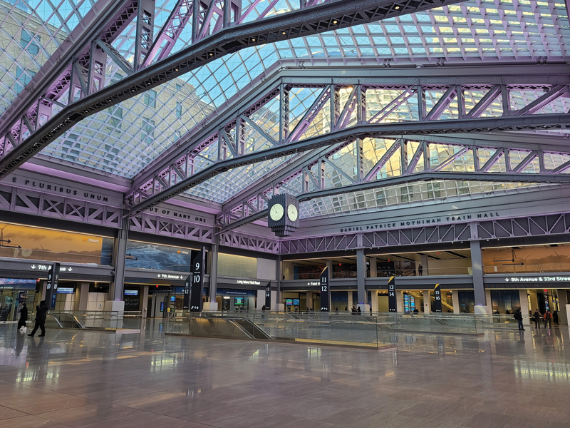
The train hall’s central feature is the main boarding concourse, designed by architect Skidmore, Owings & Merrill (SOM designed all three phases). Located in Farley’s former mail sorting room, the 150- by 200-foot space is column-free due to three existing steel roof trusses – invisible a century ago – that were uncovered and reinforced to become a significant focal point of the design. Their latticed configuration and riveted connections are reminiscent of framing in the old Penn Station and add delicacy of detail and a sense of lightness, despite their large scale.
Beyond its Beaux-Arts exterior and ornate retail post office, the Farley Building is, for the most part, more function than form. The mail sorting room was for post office employees and not a public space. Its floor was two levels above the tracks, only one level below the trusses, and the long clear spans afforded workers the flexibility needed for sorting racks, carts, conveyor belts, pneumatic tubes, and other equipment; in practice, the space was quite cluttered. The skylights were pragmatic, providing ample lighting from the sun but not intended as aesthetic elements. A ceiling of filigreed diffusers closely followed the truss bottom chords where viewing galleries were concealed, along with the full depth of the trusses. Removing the mail room floor and most of the existing roof, combined with placing the arched skylights above the truss top chords, fully utilized the available height to create a dramatically open space.
Stability and Elegance
The existing trusses had sufficient capacity to carry a new roof – the loading would be essentially unchanged. However, all existing framing between the trusses had to be removed to maximize the skylights’ function and appearance. This left them unbraced at their ends and for the full length of their gabled top chords. Restoring the trusses’ stability was a central component of the structural design by Severud Associates.

Each truss is composed of two identical and parallel bents, spaced about three feet apart, initially to form an observation gallery for postal inspectors. The bents are tied together with diaphragm plates and latticed straps that terminate about six feet above the bottom chords. A box beam 36 inches wide by 24 inches deep, composed of 3.5-inch-thick steel plates and located along the top of each truss, provides sufficient lateral support without extending beyond the width of the existing chord members. The box beams also deliver lateral loads from the skylights to the ends of the trusses and eliminate the need to provide bracing between them.

The skylights were designed by SOM in collaboration with schlaich bergermann partner, structural engineers. Four modules, each measuring 50 feet by 150 feet and arched in cross-section, follow the gabled truss top chords to enclose the concourse. The structures are lightweight grids of steel tees that vary in depth and are spaced with three to four feet between them. The frameworks are internally braced with in-plane diagonal cables and transverse “spider webs” of cables at the existing truss third points.
The trusses required additional reinforcements to maintain stability under the skylight loading. First, diaphragm plates were welded between each pair of existing truss bents, at the top of the top chords and just below them. Next, diagonal bracing plates were welded to the diaphragms to prevent rotation where the bracing cables connect. Finally, plates were welded to tie together pairs of truss bottom chords at each panel point to replace the removed gallery framing.
Existing double-bent trusses also frame the perimeter of the train hall and, as the main trusses, serve as observation corridors. They support the low roof between the skylights and Farley Building office wings and are now exposed to view. With a uniform horizontal profile but located at about the main truss bottom chord level, the perimeter trusses are too low to support the new skylights. So instead, existing columns were extended up to the box beam elevation, and new framing was installed between them. At the ends of the box beams, steel tube diagonals were welded from each side, down to the first perimeter truss panel point, to prevent rotation and transfer lateral loads into the building frame.

Reaching Great Heights
Demolishing the existing sorting room floor created a lofty space and a logistical challenge: the highest point of the skylights is 92 feet above concourse level. In response, Skanska, who, with Vornado Realty Trust and The Related Companies formed the developer-builder team, created a temporary intermediate platform 30 feet above the concourse level to facilitate reinforcement of the existing roof trusses and installation of the skylight components. The platform was designed to withstand all working loads, including the scaffold frame that held the skylight segments in place during installation, and provided workers with a secure environment while also protecting personnel below. As a result, contractors could perform multiple scopes of work simultaneously, with the added benefit of significant cost and schedule savings.

Restoring Load Paths
The existing concourse level framing consists of nine-foot-deep, riveted steel plate girders spaced at 20-foot intervals and spanning up to 70 feet in the north-south direction, perpendicular to the platforms. Because the concourse framing transferred the weight of the demolished floor over the tracks, its capacity increased proportionally – enough to support the new concourse loading without global reinforcement. However, the openings necessary for escalators – rectangular, with the long direction parallel to the platforms and hence, perpendicular to the girders – interrupt the direct load path to existing columns. Therefore, existing girders had to be cut and new transfer girders installed.
The clearances for the escalator trusses and headroom meant that notches had to be cut in the top or bottom (respectively) of existing girders. At each notch, new flange plates were welded on both sides of the existing web, and the remaining flange elements – double angles and cover plates – were welded to each other and the web. Where new loads exceeded the shear capacity of the existing web, additional web plates were added, usually extending beyond the notch to provide a transition from the full-depth to notched section.

At the ends of girders, reinforcement of the notches was usually sufficient to restore capacity and deliver loads to existing columns. Conversely, a new column was necessary where a notch occurred at a girder’s mid-span. At these locations, a new footing was placed underneath the existing platform, and a column was erected and shimmed tight to the underside of the girder before the notch was cut.
In one location, an escalator conflicted with an existing column, which had to be removed. This existing column supported a girder on the opposite side that in turn transferred other existing columns and girders, complicating the condition further. New footings were placed on both sides of the existing column’s grillage, supporting a new steel girder that bridges it. Next, a hammerhead column was erected and shimmed tight to the underside of the transfer girder. Unfortunately, there was insufficient space to connect the notched girder to the remaining framing adequately. Instead, a new column was added on the other side of the notch, between tracks, before the notch was cut.
What Was Old Is New Again
The 110-year-old James A. Farley building had become antiquated and largely abandoned. Its continued use without modifications would have been inefficient, while the complete demolition necessary for a traditional redevelopment would have been wasteful. Alternatively, renovating the building – taking full advantage of its original strengths – and repurposing it for transit, retail, and offices created a 21st-century facility that maintains its early 20th-century grandeur.■
Andrew Mueller-Lust, a former Principal of Severud Associates, also contributed to this article.