
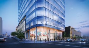
The new 95 State office and mixed-use facility consists of a 25-story Class A tower with a 5-story podium ecclesiastical meeting house totaling 640,740 square feet. The building is located in the heart of downtown Salt Lake City, Utah. The project is being developed by City Creek Reserve Inc. with Skidmore, Owings & Merrill, architect and structural engineer, and Okland Construction as the general contractor. It is scheduled for completion in late 2021. The integrated urban design of multiple project components includes a complete rehab of the interconnecting pavilion and tunnel under State Street, connects 95 State to Salt Lake’s City Creek Center, and provides connections to neighboring Harmons retail and parking with a new solar canopy. With a client and owner team interested in the long-term performance of the facility located in a region of high seismicity and close to an active segment of Utah’s Wasatch Fault zone, SOM’s structural engineering design team responded to the design challenges of the new 392-foot-tall tower constrained on a narrow corner site using state-of-the-art performance-based seismic design methodologies and standards. Figure 1 shows 95 State from the south nearing completion.
Tower Structural Systems
Designed in conformance with the 2015 International Building Code (IBC) with State of Utah 2016 Construction Code Amendments HB310, the 95 State tower and podium structure is assigned a Risk Category III per the occupancy load limits of 2015 IBC Table 1604.5. The tower superstructure uses reinforced concrete core walls as the seismic-force-resisting system extending to an overall building height of approximately 392 feet above adjacent grade with a one-level below-grade basement on the south. The site slopes up to the north approximately 15 feet along State Street, encompassing a second basement below Level 2 on the north. The height exceeds the code-prescribed height limit of 240 feet for the core-wall-only system. Therefore, the design uses a “non-prescriptive” building code design approach using an “alternate procedure” per 2015 IBC Section 104.11. The superstructure is designed based on the acceptance criteria provisions of the 2015 IBC and ASCE 7-16 standard, Minimum Design Loads for Buildings and Other Structures, Section 12.2.1.1 using PEER TBI v.2.03 (2017), Guidelines for Performance-Based Seismic Design of Tall Buildings. The ASCE 7-16 standard was adopted as a project-specific exception to the building code as recommended by PEER TBI v.2.03 Section 1.3. An independent structural design review was provided in conformance with ASCE 7-16 Sections 12.2.1.1 and 16.5 as approved by the authority having jurisdiction, the Salt Lake City Corporation.
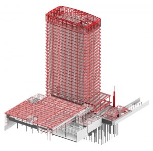
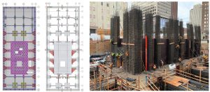
The lateral seismic-force-resisting system consists of special ductile reinforced concrete core shear walls and coupling beam construction extending from a pile and pile cap supported deep foundation system to the penthouse roof at Level 26. The slender core wall depth in the east-west direction is 33 feet, 4 inches, with an aspect ratio of 11.8. Core shear walls range from 24 to 30 inches thick with concrete compressive strength of 8,000 psi. Shear wall thicknesses are constant over the full height of core walls. The shear wall core is interconnected with ductile reinforced coupling beams at openings required for doorways and corridors. Additional openings with coupling beams were introduced to increase seismic inelastic energy dissipation. At Level 26 (El. +356.5 feet), the 2-story MEP penthouse roof lateral and gravity systems consist of a steel-framed core, roof mechanical penthouse, screen walls, and perimeter glazed wall enclosure. The penthouse lateral system combines a steel eccentric braced frame (EBF) and a moment frame structure. The EBF provides sufficient lateral stiffness while accommodating differential vertical displacements compatible with shear wall coupling beams. The moment frame provides a backup system and helps control residual drift. Figure 2 shows the overall 3-D Revit BIM model structural systems.
The office tower architectural geometry is defined by rounded glazed corner curtain wall panels with slightly articulated radiused north-south and east-west walls extending from Level 3 to 25 on the south and above Level 6 on the north. Levels 1 to 5 form a podium with larger floor areas encompassing meeting house program facilities clad typically in stone, glazing, and areas with art glass. The overall footprint is typically 109 by 210 feet in plan at the upper tower levels and 109 by 250 feet at the lower podium levels. The typical story height is 14 feet, with a story height of 12 feet 10 inches at B1, 18 feet 1 inch at Level 1, 16 feet at Level 4, and 15 feet at Level 25.
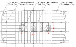
The gravity system of the tower and podium superstructure floor plates consists of perimeter steel girders that span between W14 columns located typically at 30 feet, and W18-W21 composite beams typically spaced at 10 feet spanning between the W21 girders and the central core. Figure 3 shows a typical framed tower level. The composite steel framing and slab system generally consist of a 3¼-inch lightweight concrete fill over a 2-inch metal deck. At Level 2, Level 4 mechanical rooms, and the Roof Level, the composite steel framing system consists of a 4½-inch normal weight concrete fill over a 3-inch metal deck. A 2½-inch normal weight concrete fill over a 3-inch metal deck is used at the Level 5 roof garden. At the tower’s north and south curved walls, steel framing is cantilevered up to 18 feet to allow for column-free perimeter tenant office areas.
The deep foundation system consists of 24-inch-diameter auger cast-in-place displacement piles supported on pile caps that resist superstructure gravity and lateral load reactions at the base of the building. A total of 363 piles extend into primarily gravel and clay deposits to very dense gravel layers at depths of 110 to 115 feet. In upper layers, liquefaction-induced settlements up to 1½ to 2 inches are expected. At the tower core, a single 11-foot-deep mat pile cap is provided, interconnected by tapered grade beam outriggers on primary transverse column lines to perimeter pile caps in the east-west direction, to resist lateral overturning seismic forces. Grade beams typically interconnect the pile caps and a 10 to 12-inch pile-supported suspended slab on grade. Perimeter foundation walls are also supported by a continuous grade beam that spans on perimeter piles.
Level 1 framing construction consists of cast-in-place reinforced concrete with a typical 14-inch slab, beams, drop panels, and diaphragm collector elements to transfer lateral loads from tower core walls to perimeter foundation walls. Figure 4 illustrates foundation modeling of core wall mat and grade beam outriggers.
Site Seismicity and Ground Motions
The site in downtown Salt Lake City is located within the Intermountain Seismic Belt, one of the most seismically active areas in the interior western U.S, with a repeated occurrence of earthquakes greater than a moment magnitude of M7 along the Wasatch fault zone. The site is located approximately 1.18 miles from the Salt Lake City Segment of the Wasatch Fault Zone. Seismic loads were developed utilizing site-specific horizontal acceleration response spectra to design the tower – service level earthquake (SLE) at a 43-year return period and risk-targeted maximum considered earthquake (MCER) at a 2,475-year return period by the project geotechnical engineering seismic hazard consultant, Lettis Consultants International, Inc. (LCI), in coordination with site geotechnical investigations by Consolidated Engineering Laboratories (CEL). Peer-reviewed by the Structural Design Review Panel (SDRP), 11 sets of fault-normal and fault-parallel ground motion records were chosen for MCER using the 2014 Next Generation Attenuation (NGA-West2) model, in conformance with ASCE 7-16 and by following a non-ductile spectral matching approach that conserves the correlation between horizontal components and results in time histories that have peaks and valleys.
Performance-Based Seismic Design
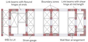
The tower seismic design is based on the PEER TBI v.2.03 (2017) performance-based guideline procedures and the SDRP review. Key unique design aspects of the project included, 1) design of an efficient and well-proportioned lateral load resisting coupled-core wall system that could dissipate seismic energy by controlled yielding of the coupling beams and hinging at the base of the building core, and 2) explicit modeling of the soil-structure interaction to capture the maximum Level 1 transfer diaphragm and basement wall backstay effects, and therefore, determine the upper-bound demands on the transfer diaphragm. The core walls are modeled using nonlinear fiber elements, and the coupling beams are modeled using lumped plasticity flexural/shear hinges in Perform-3D (CSI). Figure 5 shows the core wall horizontal section highlighting the wall fiber arrangement, coupling beams, and core wall strain gauges which capture yielding of longitudinal reinforcement. The coupling beams are modeled according to recommendations in Naish (2010), Galano and Vignoli (2000), and Lim et al. (2016). The stiffness modifiers for the component actions, where nonlinear behavior is not explicitly modeled, are used according to PEER TBI v2.03.
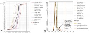
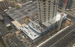
Nonlinear analyses are performed with a suite of 11 ground motions for two separate cases to bound the backstay stresses. The upper bound lateral load in the Level 1 transfer diaphragm and perimeter basement walls are modeled using the higher stiffness modifiers per ATC 72-1, Table A-3. The foundation flexibility is accounted for by using soil springs to model the vertical pile stiffness. The upper bound lateral load remaining in the shear wall core is captured using relatively lower stiffness property modifiers per ATC 72-1, Table A-3. All the elements are modeled as pinned at the top of the pile cap. The structural performance is primarily evaluated by studying the inter-story drift ratios, coupling beam rotations, strain in the core wall fibers, and rotations at the end of the gravity beams in conformance with limits imposed in the detailed structural design criteria. Figure 6 illustrates compliance to design criteria with respect to inter-story drift ratios and strain in core wall fibers. The MCER mean base shear force for the maximum backstay case is 15,250-kips (0.145g) in both the transverse and longitudinal directions. NLRHA ground motion analyses were typically completed in 3 to 4 days run-time. With the modeling of piles, run-times extended up to 40 days. Figure 7 shows the in-progress construction of reinforced concrete core walls and steel framing up to Level 6.
The new 95 State office tower and mixed-use facility is a bold and iconic addition to Salt Lake City’s downtown urban and livable city center. The performance-based seismic design approach achieves enhanced performance, reductions in embodied carbon impact, and a LEED Gold rating.■
The authors thank the client group at City Creek Reserve, Inc., for their support in achieving project goals, and the entire design and construction team for their contributions.
Whole-Building Life-Cycle Assessment
The 95 State building was evaluated for a whole-building life-cycle assessment (LCA) following LEED v4/4.1 BD+C Core and Shell, Materials and Resources (MR) – Building Life-Cycle Impact Reduction credits contributing to a project LEED GOLD certification. The life-cycle assessment included a comparative performance analysis of a baseline building and the final proposed 95 State building. The assessment measures environmental impacts of the structural systems and enclosure elements only, evaluated from cradle-to-grave over a 60-year building service life. Environmental profiles reflect the industry average in the region. The assessment methodology based on U.S. EPA’s TRACI 2.1 tool assesses impacts in six categories, 1) global warming, 2) acidification, 3) ozone depletion, 4) smog formation, 5) eutrophication, and 6) primary energy. The Athena Sustainable Materials Institute’s Impact Estimator for Buildings v.5 (2014), is used to analyze with LCI database related to basic materials, building products and components, fuel use, and transportation. The baseline and proposed buildings are functionally equivalent, of comparable size with the same gross square footage, orientation, and operational energy usage.
The 95 State baseline building design and quantities were based on prescriptive code design per IBC 2015. The superstructure consisted of gravity cast-in-place reinforced concrete slabs, joists, girders, and columns, with a reinforced concrete dual lateral resisting system including perimeter ductile moment frame beams and columns, and core walls. For the 95 State proposed building, the Athena materials concrete “mix design” database was modified to match actual “fly ash” supplemental cementitious materials (SCM) used in project specifications and confirmed through concrete mix design submittals from the concrete contractor. 95 State incorporates the following quantities of fly ash in concrete: foundation ACIP piling (20.9%); foundation pile caps, slab-on-grade, and basement perimeter walls (42.8%); superstructure core shear walls and coupling beams (29.4%); core concrete beams and slabs (20.0%); Level 1 concrete beams and slabs (28.1%); and, concrete fill on metal deck flooring (15.2% & 20.3%). Contractor concrete submittals for 95 State included NSF certified Environmental Product Declaration (EPD) documentation based on National Ready Mixed Concrete Association (NRMCA) member industry-average EPD for ready mixed concrete. EPD certification documentation included LCA methodology product standards and system boundary criteria, including A1–Raw Material Supply, A2–Transportation, and A3–Manufacturing (Core Processes). Baseline building included 10% and 20% SCM content in foundation pile and foundations to represent the standard practice to control the heat of hydration in mass concrete construction.
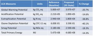
The summary results of the whole-building life-cycle assessment impact measures are shown in Figure 8, indicating significant reductions in all six categories. Per LEED v4.1, credit points are awarded for Structure & Enclosure, demonstrating greater than or equal to 10% reduction in at least three of the six impact categories. An additional point for Global Warming Potential exceeding the 20% reduction is also credited.
Project Team
Owner/Developer: City Creek Reserve, Inc., Salt Lake City, UT
Structural Engineer and Architect: Skidmore, Owings & Merrill, San Francisco, CA
General Contractor/Concrete: Okland Construction Company, Salt Lake City, UT
Prime Steel Contractor: SME Steel Contractors, West Jordan, UT
Concrete Reinforcement Detailer: Harris Rebar Inc, Salt Lake City, UT