
How many times have you designed an addition to an existing building and wondered, “What was the engineer thinking?” Many types of structures are designed for future expansion in anticipation of the ever-changing needs of the owner and community. Hospitals are frequently designed for additional floors. Structural engineers play an essential role in designing and detailing the structure to accommodate future expansion, as well as helping the owner and design team plan ahead for the intended use and functionality of the additional floors.
Building Codes
The city, county, or state in which a building resides specifies the building code used by the structural engineer. The local jurisdiction may enforce an older version of the International Building Code (IBC), even though a more recent edition has been published. When designing for future expansion, the most recent edition of the IBC and material codes should be consulted, as well as the version adopted by the authority having jurisdiction.
Most of the codes used in design publish a draft version for public review before being formally issued. Draft versions of wind speed and seismic hazard maps reveal if the wind pressures and spectral response accelerations will increase or decrease in the next code cycle.
Predicting unwritten code changes is unreasonable. However, owners should not think they are paying for a building designed for multiple floors, only to find out a few years later that not all of the future floors can be added because the engineers did not consider the most recent codes available at the time.
Design Team Coordination
During design, the architect, mechanical engineer, and other consultants typically focus on the building at hand and not the future expansion of the building. For the structural engineer, the number and extent of future floors are just the beginning of the information needed to provide a structure capable of handling a proposed future addition.
The architect must provide guidance regarding the use of future floors. If the current roof/future floor will be used for operating rooms, check the current roof for sensitive equipment vibration criteria. When future floors require a large column-free space (e.g. ballroom), design the appropriate columns and foundation for a larger tributary area. If future floors require thick-set tile, identify the locations and depths of any slab recesses. If additional stairs or elevators will be added with the future floors, decide if they will be inboard or outboard of the building. If they are located within the footprint of the current building, discuss whether the spaces will be kept open or if knock-out slabs will be used so the spaces can be used for storage or other purposes.
Medical office buildings are frequently located adjacent to a hospital. Office buildings may be a business occupancy, Type IIA or IIB construction type, and be classified as Risk Category II in which case a firewall is sometimes needed. The neighboring hospital is commonly institutional occupancy, Type 1A construction, and Risk Category III or IV. If hospital programming might spill over into the medical office building in the future, the office building should be designed for the same construction type, occupancy, and risk category as the hospital.
When planning for future expansion, the architect may have renderings depicting the final height and look of the building. The architect needs to explicitly define the future floor heights, cladding, and which stairs or elevators will need to serve the roof. Parapets and screenwalls can add a significant amount of wind load to the building. They should be discussed with the owner and architect to ensure the lateral load-resisting system is designed properly.
In high-rise construction (buildings with occupied space over 75 feet above the lowest level with fire truck access), the stairs must be pressurized per IBC 403.5.4. A building without the future floors may not be classified as high-rise. However, stair pressurization may be required after the structure is expanded vertically. During the original design, space should be allocated on each floor for the stair pressurization chases and not treated as an afterthought when the future floors are added.
Elevator hoistway sizes and pit depths should accommodate both the present and future travel distance, weight, and speed requirements. The roof framing above the elevators should be laid out to match the typical floor framing; a knock-out slab should be provided so the contractor can easily saw cut the slab to match the hoistway size below and extend the elevator vertically. If a doghouse is required in the elevator penthouse to meet the elevator overrun requirements, the penthouse roof should be designed for the same loading as the penthouse floor; only one floor may be added in the future even if the building is designed for multiple additional levels.
The mechanical design of the built-out project has structural implications that need to be addressed in the original design. Will there be a mechanical room on each floor? Will there be a mechanical penthouse or rooftop units on the future roof? The size, location, and anticipated equipment weights are required for the column and foundation gravity design and the seismic lateral design. Furthermore, rooftop equipment and whether it is screened can have a significant effect on the lateral design due to increased wind loading.
The roof beams of a mechanical penthouse may need to be designed for the same equipment loading if the penthouse moves up in the future instead of staying in place. Knock-out slabs may be needed at future mechanical chases. The phasing of the future construction must be considered as well. A rooftop unit should not be located over one of the building columns because vertically extending the structure will require shutting down and removing the unit.
Design Considerations
Once the scope of the future expansion has been finalized with the design team, the structure can be properly designed and detailed. For the sake of the owner and subsequent design team (hopefully you!), the structural drawings should clearly depict the future expansion capabilities of the structure via a future key plan and supplemental notes. On a recent healthcare facility in Florida, the authors designed a one-story portion of a hospital for six future floors. The design team allocated space for a mechanical room on each floor, and the columns and foundations were designed accordingly. The future key plan on the structural drawings clearly indicated the locations of those future mechanical rooms in addition to the extent of the expansion.
The design of the current roof structure needs to consider both the present and future conditions; the future use of the framing as a floor does not always govern the design. Designing roof framing for snowdrifts is one example. A one-story building that is designed for only a portion of the footprint to expand vertically will create snowdrifts on the roof areas that have no potential future expansion. On a project the authors designed in Alaska, a one-story building was designed for one future floor. The design of the roof beams was controlled in some areas by large snowdrifts adjacent to stair and mechanical penthouses in the present case. Similarly, when a roof level has mechanical equipment and screenwalls in the present case, the design of the structure considering only the future floor loading may be inadequate.
When designing the exterior wall studs or furnishing exterior wall component and cladding wind pressures for the stud supplier, the wind pressures should be based on the future building height. Exterior wall studs designed for just the current building height may be inadequate for the higher leeward wind pressures after the additional floors have been added.
The topped-out structure will control the design of most of the lateral system components. However, there are instances when the present case impacts lateral design. The chord and collector diaphragm forces at the current roof in the present model may be larger than the forces at that level when it is an intermediate floor in the future model due to a different distribution in lateral forces. There may be a torsional irregularity in the present case that is not apparent in the built-out model but would warrant using modal response spectrum analysis.
Special Detailing
Columns designed for future expansion are typically detailed to extend above the top of the roof slab. Column extensions of just a couple of inches will be contained within the roofing material and will not be visible. Extending the column in the future will require disturbing the roofing at each column location. Column stubs that extend 18 to 24 inches above the roof slab will not compromise the roofing system during future construction but will be visible.

Figure 1. Cap plate detail at future steel column.
For steel columns, a cap plate is usually placed on top of the column to allow for tolerances during the erection of the future column (Figure 1). For projects that must comply with AISC 341, Seismic Provisions for Structural Steel Buildings, Section D.2.5 requires all column splices be located four feet away from the beam-to-column flange connection. One of the exceptions allows the splice to be located closer if the column splices are made with complete penetration welds, but cannot be less than the depth of the column.
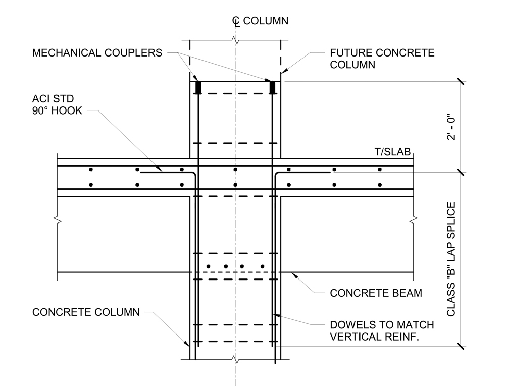
Figure 2. A section at future concrete column.
Concrete structures can be designed for future floors of either structural steel or concrete. For future concrete floors, mechanical couplers can be used at the top of the column, as shown in Figure 2. The roof of a concrete structure is typically not designed for shoring loads, and re-shores are not permitted because the uppermost floor of the building is occupied. Therefore, the future formwork will need to span between the future columns after they are placed. Alternatively, concrete structures can be designed to expand vertically in structural steel. The size of the future steel base plate relative to the concrete column and how the lateral loads are transferred between the steel and concrete structures will determine the column detail. At moment frames, it may be beneficial to encase the first lift of steel columns in concrete and locate the anchor rods inboard between the column flanges as depicted in Figure 3.
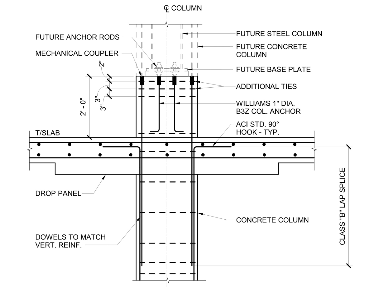
Figure 3. A section at future concrete-encased steel column.
The detailing of the cladding must consider future expansion. The head of a curtainwall system is often located below the roof slab and metal studs used to form a parapet. If the curtainwall system extends vertically in the future, the slab edge condition that suited the metal stud parapet may be incompatible with the curtainwall. When the stud parapet is removed, the size of the curtainwall may require the slab edge to be sawcut to allow the curtainwall to bypass the slab edge.
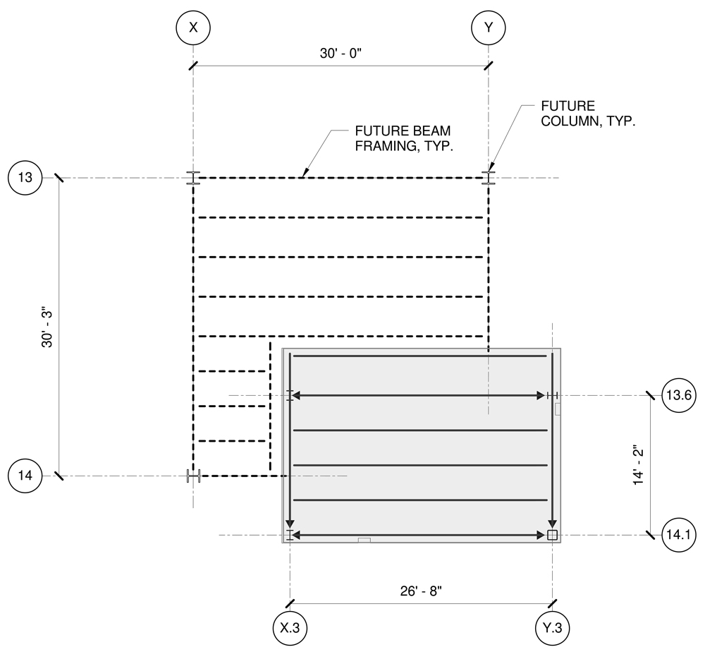
Figure 4. Framing plan depicting future beam layout.
Ideally, penthouses will be extensions of the building columns and not require cantilevered roof framing or stub columns. For cantilevers or stub columns, the drawings should clearly denote how the roof framing was designed. For example, a cantilevered penthouse roof beam could either be designed for a future point load from a new shear connection, designed to be cut and removed, or it could be complete penetration-welded to a new beam and become continuous. A simple diagram on the drawings can provide the design intent as depicted in Figure 4. Similarly, stub columns used to support penthouse framing can either be designed to remain or be removed in the future.
Successful Expansions
Thoughtfully addressing the design and detailing of structures with future expansion capability increases the likelihood of a successful addition down the road.■