
Wood studs designed to resist wind loads in either loadbearing or non-loadbearing tall wall applications are good examples of resilient design. Tall walls can be defined as those exceeding the International Residential Code (IRC) prescriptive limit of 10 feet for loadbearing walls. Proper design of wood structures to resist such wind loads also requires correct use of wind load provisions. Minimum design loads must be in accordance with the governing building code or, where applicable, other recognized minimum design load standards such as American Society of Civil Engineers’ ASCE 7 Minimum Design Loads for Buildings and Other Structures. Wind load provisions have been developed for design of major structural elements using “main wind-force resisting system” (MWFRS) loads and secondary cladding elements using “component and cladding” (C&C) loads. Elements and subassemblies receiving loads both directly and as part of the MWFRS – such as wall studs – must be checked for both the MWFRS loads and C&C loads, independently.
Studs should be designed using MWFRS pressures when considering the combined interactions of axial and bending stresses; and designed using C&C pressures when considering axial or bending stresses, individually. This interpretation was developed because only MWFRS pressures provide loads which have been temporally and spatially averaged for different surfaces (MWFRS loads are considered to be time-dependent). Since C&C loads attempt to address a “worst case” loading on a particular element during the wind event, these loads are not intended for use when considering the interaction of loads from multiple surfaces (C&C loads are not considered to be time-dependent).
This is not unusual. In most cases, it can be considered the controlling limit in wind design of loadbearing and non-loadbearing exterior studs. However, until sufficient boundary conditions are placed on this simplification, both MWFRS and C&C load cases should be considered.
Resources
The American Wood Council (AWC) has developed several code-referenced design standards for wood construction, for a variety of building types, to aid structural engineers in addressing the challenges associated with high wind.
The National Design Specification for Wood Construction (NDS®) includes necessary design procedures and design value adjustment factors for wood products. The design values for wood studs and the beam and column buckling formulas used to design studs for axial and lateral loads are incorporated in the NDS.
The Special Design Provisions for Wind and Seismic (SDPWS) provides specific design procedures for wood members, fasteners, and assemblies to resist wind and seismic forces. In addition to shear wall and diaphragm design, SDPWS offers design criteria for members and connections subject to out-of-plane wind loads. One very specific provision pertinent to tall wall design is the wall stud bending strength and stiffness design value increase, where reference bending and bending stiffness values are permitted to be increased based on the presence of exterior wood structural panel sheathing and interior gypsum wallboard with specific attachment requirements.
The Wood Frame Construction Manual (WFCM) is another AWC standard integral to wood design, providing engineered and prescriptive design requirements for one- and two-family dwellings. However, it also serves as a useful tool in the design of non-residential buildings in Risk Category I or II that fit within the WFCM scope of building size and assigned loads. Examples include buildings where the bottom floor is used for stores, offices, and restaurants. For buildings within its scope, WFCM contains both engineered and prescriptive solutions for wind, seismic, and gravity loads. The engineered provisions in WFCM Chapter 2 offer, for example, tabulated wind loads and gravity loads based on assumptions from ASCE 7 provisions.
Prescriptive wood solutions in Chapter 3 tabulate both loadbearing and non-loadbearing stud lengths for common lumber species resisting wind loads for various deflection limits and sheathing types. For the prescriptive solutions in WFCM Chapter 3, loadbearing walls are limited to a maximum of 10 feet, while non-loadbearing walls can be 20 feet tall.
In Chapter 2, WFCM permits loadbearing studs up to 20 feet tall. For C&C wind pressures, the localized bending stresses are computed independent of axial stresses. For MWFRS pressures, bending stresses in combination with axial stresses from wind and gravity loads are analyzed. For buildings limited to the conditions in WFCM, the C&C loads control the stud design. A comprehensive WFCM Commentary provides all the background assumptions and example solutions for the tabulated values.
Design Example
The following loadbearing stud wall design example demonstrates standard design checks for limit states of strength and deflection based on methods outlined in AWC’s 2015 NDS, 2015 SDPWS, and 2015 WFCM Workbook, along with ASCE 7-10 (see end note).
The objective is to design a 19-foot tall loadbearing wall stud in a two-story building with a 25-foot mean roof height, 32-foot roof span, and 2-foot overhangs. Wind loads are 160 mph Exposure B. Additionally, the following gravity loads are assumed for the roof:
- dead load = 10 psf
- live load = 20 psf
- ground snow load = 30 psf
These loads are assumed for the attic and ceiling:
- dead load = 15 psf
- attic live load = 30 psf
The approach is to analyze wall framing as part of the MWFRS exposed to in-plane and out-of-plane load combinations specified by ASCE 7-10. Studs are then analyzed with out-of-plane C&C wind pressures only. The analysis involves an iterative approach. Initial values are selected for member properties (depth, number of members, species, and grade), and analyses completed. Then, stresses and deflections are determined and compared to allowable values. At this point, the member properties are varied, with analyses repeated until stress and deflection criteria are satisfied.
Southern pine No. 2 grade 2x8s are analyzed assuming 16-inch-on-center (o.c.) spacing, wood structural panel exterior sheathing, and ½-inch gypsum wallboard interior sheathing with the following reference design values from the 2015 NDS Supplement Table 4B:
- Fb = 925 psi
- Fc = 1,350 psi
- E = 1,400,000 psi
- Emin = 510,000 psi
The wall stud bending strength and stiffness design value adjustment factor from SDPWS Table 3.1.1.1 for a 2×8 is equal to 1.25. Load duration factors (CD) apply to the bending and compression design values, but not modulus of elasticity. CD also varies depending on the shortest load duration in the load combination, for load combinations including:
- wind, CD = 1.6
- roof live loads, CD = 1.25
- snow loads, CD = 1.15
Allowable Stress Design (ASD) load combinations per ASCE 7-10 are evaluated for this example (Figure 1). Both balanced and unbalanced snow loads are analyzed. For this example, an unbalanced snow load of 360 plf provides the highest snow loads on the studs.
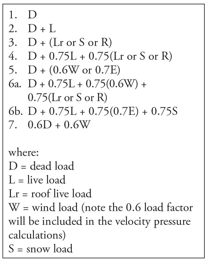
Figure 1. Evaluation of ASD load combinations.
MWFRS wind pressures are calculated using the “envelope procedure” contained in ASCE 7-10 Chapter 28. The velocity pressure exposure coefficient for a building located in Exposure B with a 25-foot MRH is 0.70 per ASCE 7-10 Table 28.3-1, and a factor of 0.6 adjusts the pressures associated with a 700-year mean return period wind to allowable stress design. The velocity pressure calculates to 23.4 psf.
ASCE 7-10 Figure 28.4-1 shows the external pressure coefficients for interior and end zones for two cases – winds generally perpendicular to the ridge and winds generally parallel to the ridge. Wind perpendicular to the ridge produces the highest external wall pressure coefficients. Reactions at the top of the bearing wall are determined by summing overturning moments about the top of the leeward wall for both load cases and determining the controlling reaction to use in the design. Horizontal projections are used in the analysis. The out-of-plane MWFRS pressure on the wall at interior zones is calculated as 17.3 psf.
Load Combinations 1, 2, 3, and 4 model gravity-only loads (dead load, live load, and/or snow load). Load Combinations 5, 6a, and 7 include MWFRS loads. Load Combination 6a controls for the load combinations that include wind loads. The bearing walls must resist distributed loads from the attic floor and roof and out-of-plane MWFRS loads proportional to the width of their tributary areas. Using NDS column, beam, and combined bending and axial load provisions, the interaction value calculated per NDS Equation 3.9-3 is 0.46.
ASCE 7-10 provisions for calculating C&C loads are used assuming a minimum effective wind area of (L)2⁄3. By observation, negative external pressure coefficients are greater than positive external pressure coefficients. Thus, negative external pressures and positive internal pressures (windward) create the greatest C&C pressures. A C&C pressure of -25.5 psf is calculated for this example. Applying the C&C pressure as a bending load on the studs leads to calculation of a bending stress to bending strength ratio of 0.76 – even larger than the combined bending and axial interaction calculated with MWFRS loads. Therefore, No. 2 grade southern pine 2×8 studs work from a strength standpoint.
A deflection check using C&C loads reveals an H/Δ of 273 for No. 2 grade southern pine 2×8 studs. Assuming either a flexible finish or gypsum-type finish, code deflection limits are typically H/180 and H/240, respectively. Therefore, the 2×8 studs are adequate for deflection unless a brittle finish requiring a tighter deflection limit is used.
Conclusion
Major structural elements should be designed for MWFRS loads, and secondary cladding elements should be designed for C&C loads. Components and assemblies receiving loads both directly and as part of the MWFRS should be checked for MWFRS and C&C loads independently. In cases where components and assemblies must be designed for lateral wind loads, the controlling design case will often be wind acting alone. However, each load combination should be considered thoroughly before being dismissed.▪
This article’s example is based on a webinar, Design of Loadbearing Tall wood Studs for Wind and Gravity Loads (DES230), available for free at www.awc.org. Due to space constraints, only highlights of the example are presented here, but full details can be found in the webinar materials.