
New Life for the Pierceville Bridge
The 113-foot Pierceville Bridge was built in 1881 to carry SR-1029 over Tunkhannock Creek in Wyoming County, Pennsylvania. The Pierceville Bridge is a rare lenticular truss bridge, so-called because the top and bottom chords of the trusses create a distinctive “lens” shape. The single span bridge is 113 feet 8 inches long with a width of 14 feet 9 inches between centers of trusses. Only five lenticular truss bridges remain in Pennsylvania, including the well-known Smithfield Street Bridge in Pittsburgh. The Pierceville Bridge is also noteworthy because it is the oldest lenticular truss bridge in Pennsylvania and one of the oldest lenticular truss bridges in the United States. It was built by the Corrugated Metal Company of East Berlin, Connecticut, which later changed its name to the Berlin Iron Bridge Company and was a promoter of this bridge type. The company held rights to inventor William Douglas’ patent for a distinctive variety of lenticular trusses. Except for the Smithfield Street Bridge, which was designed by Gustav Lindenthal, all other surviving lenticular truss bridges in America were designed and built by the Corrugated Metal/Berlin Iron Bridge Company.
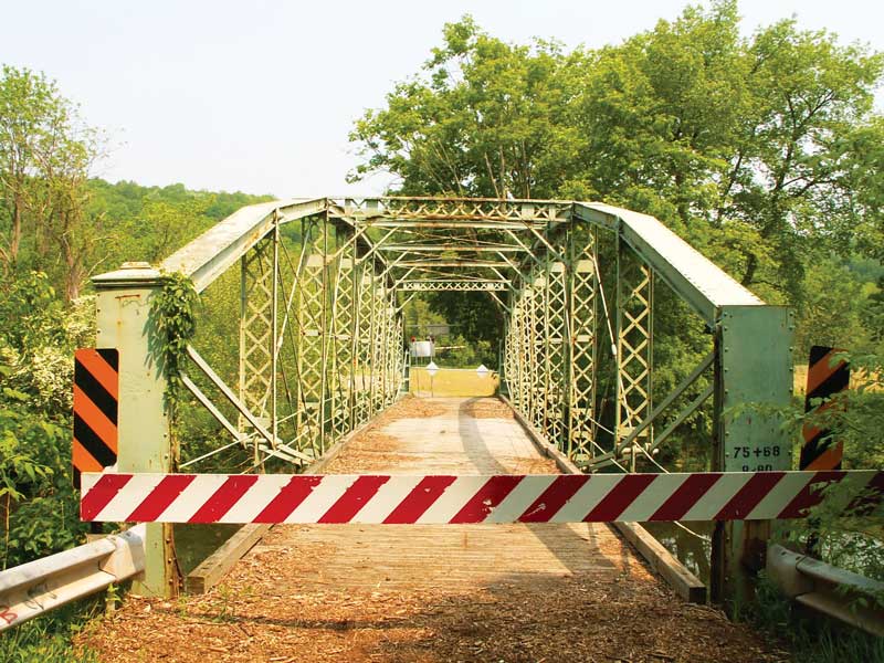
Pierceville Bridge before.

Pierceville Bridge after.
The Pierceville Bridge served traffic in its original location until 2005, when deck, stringer, and floorbeam deterioration prompted the closure of the bridge to traffic. The bridge remained closed in this condition, with no repairs made for several years, while a plan could be developed to determine the best course of action going forward. In 2011, the Pennsylvania Department of Transportation (PennDOT) initiated a study to reopen the crossing to traffic, while also addressing the need for farm equipment, emergency vehicles, and school buses to cross the bridge. The bridge’s maximum twenty-ton rehabilitated capacity, 9.5-foot overhead clearance, and 12.3-foot one-lane roadway were obstacles to finding a way for the lenticular truss to meet these needs. Because the bridge was considered eligible for listing in the National Register of Historic Places, a Section 106 Review was required by the FHWA to consider feasible and prudent alternatives to meet the project purpose and need, while avoiding adverse effects (such as demolition or alteration) of the historic bridge. During this process, it was determined that the bridge could not be rehabilitated to the project specifications. However, it was discovered that Tunkhannock Township, less than ten miles away, was interested in relocating and preserving the historic bridge for pedestrian use in Lazy Brook Park over a flood relief channel of Tunkhannock Creek. Through additional discussions during the Section 106 review, it was agreed that the bridge was a suitable candidate for relocation and reuse as a primarily pedestrian facility in the park.
Additionally, the project design team agreed that an in-kind restoration rather than rehabilitation was appropriate for this exceptional historic bridge. This meant that above-average attention to detail would be paid to maintaining the original bridge by retaining original materials whenever possible and attempting to use exact replicas for any elements requiring replacement. In particular, this included the use of hot-driven rivets matching the existing bridge rivets, instead of modern bolts typically used on projects involving riveted truss bridges. While already practiced in several other states, this in-kind restoration was a first for PennDOT. The decision to relocate and preserve the historic bridge avoided adverse effects, while also allowing for construction of a new modern bridge on SR-1029 that met the purpose and need of that location.
The $3M project included the relocation and restoration of the Pierceville Bridge and construction of the new replacement highway bridge on SR-1029. The first step of the historic bridge portion of the project was the removal and non-destructive disassembly of the historic truss bridge. After the timber deck was removed, the approximately 54,000-pound truss bridge was lifted off its abutments and moved to a nearby laydown and disassembly area. The process involved using a 500-ton crane and a specialized steel lifting frame that had been designed and fabricated to act both as a spreader beam system for the lift and as a disassembly/assembly jig (Figure 1). After the crane had moved the bridge and lifting frame to the laydown area, vertical steel columns were attached and the whole structure was laterally braced with guy wires anchored to concrete deadmen. This transformed the lifting frame into a supporting structure from which the truss hung, enabling safe disassembly of the truss. The third and final use of the steel support structure was to provide the structural support for the containment system necessary to blast the lead-containing paint off the bridge to protect workers and the environment before disassembly.

Figure 1. Removal of the bridge from its original location. Courtesy of McCormick Taylor.
After removal of the steel deck stringers, disassembly of the truss itself was completed generally from the bottom to the top, with the floorbeams, lower bracing, and lower chords removed first (Figure 2).

Figure 2. Disassembly of the bridge. Courtesy of Bach Steel.
This was followed by removal of the truss vertical and diagonal members, and finally separating the upper chord splices. As a pin-connected truss, the primary method of disassembly was to remove the pins. The original pins were designated to be replaced to facilitate this process, allowing for flame cutting of the pins into pieces that could then be more easily driven out of the members. The cast iron pin caps were to be reused and therefore had to be unbolted and saved. Bolts, turnbuckles, and threaded rods on the bridge were carefully heated to expand and loosen them, enabling their removal. Once removed, the threads of the nuts and bolts that had remained sealed from the elements for over 135 years displayed a like-new appearance. As the bridge was disassembled, each part was marked with a numbered tag to not only assist with reassembly but to also identify any parts designated for repairs.
The structural members of the truss are made of wrought iron, confirmed through chemical and metallurgical testing. The higher slag (silica) content of wrought iron offers better resistance to corrosion than steel, and this was apparent in the condition of the Pierceville Bridge. Most of the deterioration on the bridge was in areas subject to moisture retention such as floorbeams, end posts, and areas that had suffered mechanical damage caused by floods and traffic impacts. Several lower chord eyebars were replaced out of an abundance of caution due to possible cracks in the heads. However, the vast majority of eyebars on the bridge were in outstanding condition with minimal to no section loss, even in the traditionally troublesome areas at the pin connections where the stacked eyebar heads often develop section loss while in contact with adjacent eyebars and members.

Figure 3. Completed shop repairs of vertical members. New steel is painted grey in this photo. Courtesy of Bach Steel.
The built-up vertical members and portal bracing on the bridge were in good condition overall. However, some sections had been impacted by vehicles, and one vertical member had been crudely repaired with welded splices in the angles. Rather than completely replace these damaged members, a partial replacement was undertaken. The impacted and poorly repaired areas of the verticals were removed and replaced with new steel riveted to match the original sections (Figure 3). Similar repairs were made to the portal bracing. The bridge’s floorbeams are built-up, variable depth, “fishbelly” shaped beams. Some of them had section loss on the angles and at the lateral bracing connections. Deteriorated angles were removed and replaced with new angles riveted to the beams. The lateral bracing connection areas were strengthened by adding a small riveted plate to provide additional cross-sectional area. Once the top chord splices were disassembled, cracking between rivet holes was discovered. The original splice plates were replaced with slightly larger plates to develop a friction connection that would provide a secure splice, to avoid having to replace these members or rely on a welded repair.
Two parts of the riveted truss were replaced in their entirety with replicas. The longitudinal edge bracing that parallels the edges of the deck had suffered considerable damage from floods over the years. As a result, the bracing was replaced with new riveted edge bracing, matching the original design of two paired angles with v-lacing. Also, the end posts of the truss had impact damage as well as moisture-related deterioration, so all four end posts were replaced with new riveted end posts. The Pierceville Bridge made use of cast iron in a few areas of the bridge including pin caps, end post caps, and builder plaques.
A handful of these cast iron elements on the bridge had been damaged or were missing. These were replicated in steel using surviving original castings as templates.
One minor area of deviation from the original truss design occurred with the lower lateral bracing. With the original bracing deteriorated and damaged from floods, new lower lateral bracing was required. However, the original lower lateral bracing was composed of wrought iron rods with loop-forged eyes. Wrought iron is not available commercially in the United States, and loop-forges are extremely difficult to fabricate using steel. As a result, the new rods were fitted with a clevis at each end in lieu of forged eyes.
Repairs to the historic truss were completed in a shop setting using new fabricated steel supplied to the repair contractor by a PennDOT-approved fabricator. Special provisions in the contract ensured that the rivets and associated repair work were completed by a firm with extensive prior experience. Since riveting is not part of typical bridge construction projects today, the standard bridge prequalification classifications used by transportation departments do not consider riveting experience. Rivets for the Pierceville Bridge were driven according to standard specifications including ASTM A 502 and ANSI Standard B18.1.2. The rivets were heated in a gas forge and driven with hydraulic riveters and pneumatic rivet hammers depending on the location and accessibility of the rivet being driven (Figure 4). Care was taken to closely match the new rivet head size and style (dome top versus countersunk) to the original rivets.
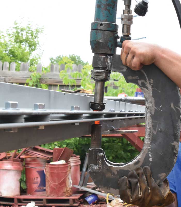
Figure 4. Shop riveting a new edge bracing member using a hydraulic riveter. Courtesy of Bach Steel.
While repairs to the truss were underway, abutment construction was accomplished at Lazy Brook Park, the new home for the historic bridge. A noteworthy aspect of this work was that the new concrete abutments were faced with some of the original stones that had been salvaged from the dry-laid stone abutments at the original bridge location. The original stones were transported to the new site, cleaned, cut down to an approximate 6-inch thickness, and attached with mortar to the freshly cast concrete abutments. This had the benefit of preserving some of the original abutment materials and also provided a more realistic simulation of a stone abutment.

Figure 5. The restored truss is placed on the new abutments at Lazy Brook Park. Courtesy of McCormick Taylor.
Following completion of repairs, the truss parts were shipped to a paint shop to be blasted again and painted with a 3 coat inorganic zinc rich paint system. Once complete, the parts were shipped to their new home. The reassembly of the truss at Lazy Brook Park was essentially a reversal of the disassembly process, using the same temporary support and lifting frame system. This was followed by the setting of the truss onto its new abutments with the use of a smaller, 150-ton crane due to a much shorter lifting radius (Figure 5). Once the truss was in place on the new abutments, the new timber stringer, deck, and railing system were installed. The new deck is an all-timber system composed of pressure-treated Southern yellow pine; including 12- x 4-inch deck stringers, 10- x 3-inch deck planks, and pedestrian railing which provides a 10-foot walkway from curb to curb (Figure 6). The use and detailing (size and spacing) of the structural timbers for the stringers and planks were intended to mimic what is thought to have been originally installed on the truss, in a further effort to be historically accurate.

Figure 6. The completed Pierceville Bridge at Lazy Brook Park. Courtesy of McCormick Taylor.
In its new location, the bridge is a centerpiece landmark and attraction. The bridge was painted a vibrant red to catch the attention of park visitors and highlight the bridge’s distinctive lenticular truss. Interpretive signage, which is mounted on a salvaged section of one of the original truss bridge end posts, informs park visitors of the bridge’s history and significance. The overall project represents a positive outcome for all involved, by providing SR-1029 with a new bridge meeting the needs of that roadway and preserving one of the rarest historic truss bridges in Pennsylvania.▪
Project Team
McCormick Taylor was the consulting engineer for this project, providing services from the initial feasibility study through the final design of both the in-kind restoration and replacement structure. Kriger Construction of Dickson City, Pennsylvania, was the prime contractor for the project. The disassembly/reassembly of the truss, as well as the shop repairs including all hot rivet work, was subcontracted to Bach Steel of Holt, Michigan. The author is grateful for the assistance from Bach Steel and McCormick Taylor in providing photos and details of the project and the work involved.