
Determining Preliminary Joint Sizes
The overall integrity and performance of a special moment frame, which is required in buildings assigned to Seismic Design Category (SDC) D, E, and F, is dependent on the behavior of the beam-column joints in the frames. The inelastic rotations at the faces of the joints produce strains in the beam longitudinal reinforcement well in excess of the strain corresponding to the yield strength of the reinforcement. As such, joint shear forces are calculated using a stress equal to 1.25fy in the beam longitudinal reinforcement that passes through the joint. Determining the adequacy of the joints in a special moment frame should occur early in the design phase because column sizes, beam sizes, concrete strength, or a combination thereof may need to be adjusted to satisfy joint shear strength requirements. A modification in member size generally requires reanalysis of the structure.
General Design Procedures
Typically, member sizes in a special moment frame are initially estimated based on experience or on serviceability requirements. It is common to go through many iterations before reasonable member sizes are established. General guidelines for overall economy should also be used in determining initial member sizes; for example, the maximum longitudinal reinforcement ratios in the columns and beams should be no more than about 2% and 1%, respectively. Architectural limitations may also have an impact on cross-sectional dimensions of these members.
Once preliminary member sizes are obtained, seismic forces are determined and a lateral analysis of the building is performed. Drift requirements are checked and member sizes are adjusted accordingly. Beam design proceeds in accordance with the American Concrete Institute’s ACI 318-14, Building Code Requirements for Structural Concrete and Commentary, Section 18.6, and the required amounts of negative and positive longitudinal reinforcement are determined at the critical sections of the beams.
After all of this, the shear strengths of the joints are checked. Often, the shear requirements are not satisfied, and the design process outlined above must be performed again using revised member sizes or revised areas of longitudinal reinforcement, or both. To help expedite the overall process, a relationship between the required joint area and the area of the beams framing into the joint can be established based on joint shear strength requirements. Preliminary member sizes can be obtained using the following procedure. Based on those sizes, interstory drift requirements can then be checked, and member sizes can be adjusted accordingly prior to final design and detailing if required.
Approximate Method
Consider the free-body diagram of a typical interior joint in a special moment frame where beams frame into opposite faces of the joint in the direction of analysis (Figure 1). The required joint shear force, Vj, is determined from equilibrium assuming flexural yielding occurs at the ends of the beam that frame into the joint (that is, the probable flexural strengths Mpr = As(1.25fy)(d-a⁄2) of the beams are developed at the faces of the column).
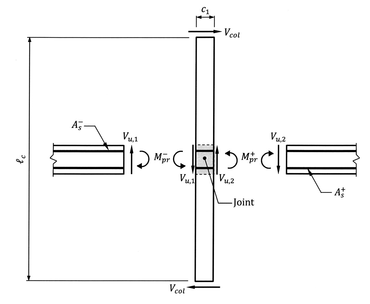
Figure 1. Free-body diagram of an interior column in a special moment frame.
For columns above the first story, it is reasonable to assume that points of inflection occur at the midheight of the column, as indicated in Figure 1. Thus, the length, lc, is equal to the depth of the beams plus one-half the clear story height above and below the joint. The shear force in the column, Vcol, can be obtained by summing moments about the center of the joint:
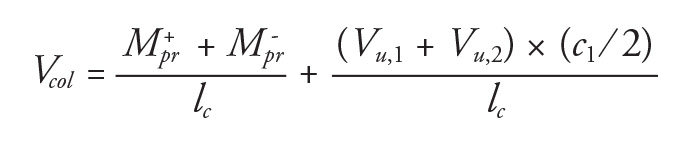
In this equation, M+pr and M–pr are the positive and negative probable flexural strengths, respectively, of the beams framing into the joint and Vu,1 and Vu,2 are the corresponding design shear forces due to the factored gravity loads and the probable flexural strengths.
Joint Shear
The joint shear, Vj, is obtained from equilibrium of horizontal forces on the joint. A free-body diagram of the joint in Figure 1 is depicted in Figure 2, where it is assumed that any axial forces on the beams are negligible. To satisfy equilibrium, the flexural compressive force in the beam on one side of the joint must be equal to the flexural tension force on the same side of the joint. When calculating the force in the beam longitudinal reinforcement, the stress must be set equal to 1.25fy in accordance with ACI 18.8.2.1; this multiplier considers the likelihood that, due to strain hardening and actual yield strengths greater than the specified value, larger tensile forces can develop in the bars which would result in larger shear forces in the joint.
The following expression for Vj is obtained by summing forces in the horizontal direction: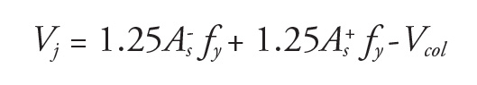
A similar set of equations can be derived for sidesway in the opposite direction. Where the same top reinforcement and the same bottom reinforcement are used in the beams on both sides of the joint, the above derivation is also valid for sidesway in the opposite direction.

Figure 2. Shear force in an interior joint of a special moment frame.
For columns in the first story of a moment frame or for moment frames where the above assumption regarding the location of the inflection point is not valid, similar analyses can be performed to determine Vj using appropriate assumptions for the case at hand. Overall analysis of the moment frame can be used as a guide to locate points of inflection in the columns.
Shear strength requirements for joints in special moment frames are given in ACI 18.8.4. In general, the shear strength of a joint is a function of the concrete strength and the cross-sectional area of the joint only. Tests have shown that joint shear strength is not altered significantly with changes in the amount of transverse reinforcement, provided a minimum amount of such reinforcement is present in the joint.
The required shear force, Vj, must be less than or equal to the design shear strength, φVn, where φ = 0.85 in accordance with ACI 21.2.4.3 and Vn is determined using the requirements in ACI 18.8.4.1:
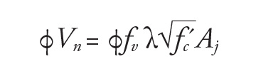
In this equation, fv is a strength coefficient that is defined in ACI Table 18.8.4.1 based on the joint configuration: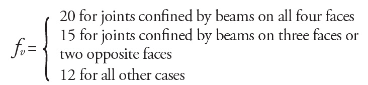
A joint face is considered to be confined by a beam if the beam width is at least three-quarters of the effective joint width (ACI 18.8.4.2).
The effective joint area, Aj, is defined in ACI 18.8.4.3 and is equal to the area of the column where beams are as wide as or wider than the column in the direction of analysis. Wider beams typically result in overall economy and help reduce congestion.
When checking shear strength requirements, it is conservative to assume that the shear force, Vcol, is equal to zero (Figure 2). Therefore, Vj can be determined from the following equation where ρ– = A–s/bwd and ρ+ = A+s/bwd are the longitudinal negative and positive reinforcement ratios in the beam, respectively:![]()
Assuming d ≅ 0.9h and Grade 60 reinforcement, the above equation for Vj reduces to the following:
Vj = 67.5Abρj
where Vj has the units of kips. In this equation, Ab = bwh is the area of the beams framing into the joint (it is assumed that the beam size is the same on both sides of the joint) and ρj = ρ– + ρ+ is the sum of the negative and positive longitudinal reinforcement ratios for the reinforcement that passes through the joint.
Assuming the effective area of the joint, Aj, is equal to the area of the column, Ac = c1 × c2, the following equation must be satisfied for joint shear strength, assuming normal weight concrete: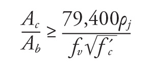
Reinforcement Ratios
It is evident that the ratio discussed above is a function of the total amount of beam longitudinal reinforcement that passes through the joint. Minimum reinforcement in accordance with ACI 9.6.1.2 must be provided at both the top and bottom of the beams. Also, for overall economy, it is advantageous to design beams such that all sections are tension-controlled. Therefore, the maximum reinforcement ratio should be taken as the tension-controlled reinforcement ratio ρt = 0.319β1 f´c ⁄ fy instead of 0.025 given in ACI 18.6.3.1 where β1 is defined in ACI 22.2.2.4.3. Thus, a range for both ρ– and ρ+ is established. Also, ACI 18.6.3.2 requires that the positive nominal flexural strength, Mn, at the face of a joint be greater than or equal to one-half of the negative flexural strength, M–n, at that joint. This roughly translates to ρ+ ≥ ρ–/2. Finally, it is good practice to use a longitudinal reinforcement ratio of no more than about 1% for the negative flexural reinforcement in a beam in a special moment frame; among other things, limiting the amount of flexural reinforcement helps alleviate congestion at the joints. The above reinforcement range, the requirement in ACI 18.6.3.2, and the guideline regarding a reinforcement ratio of 1% can all be used in establishing an appropriate value of ρj, which is needed to determine Ac/Ab.
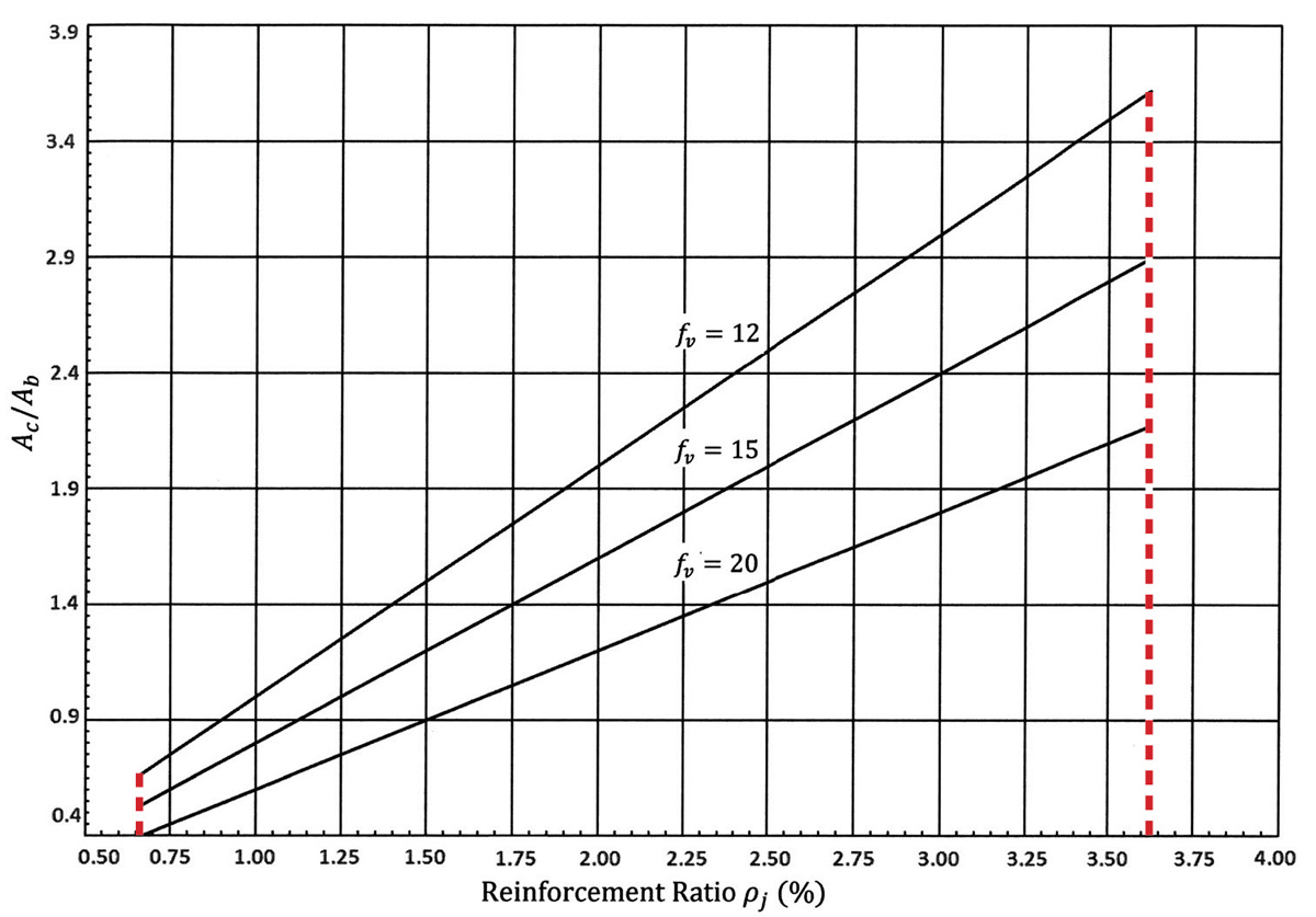
Figure 3. Preliminary joint size in a special moment frame.
Depicted in Figure 3 is the ratio Ac/Ab as a function of the reinforcement ratio, ρj, for each of the three strength coefficients, fv, assuming the following:
- Normalweight concrete with f´c = 4,000 psi
- Grade 60 reinforcement
- Beam width, bw ≥ Column width, c2
The vertical dashed lines in Figure 3 correspond to the minimum and assumed maximum reinforcement ratios ρj,min(%) = 0.33 + 0.33 = 0.66% and ρj,min(%) = 1.81 + 1.81 = 3.62%, respectively. Given a beam size that has been established based on strength and serviceability requirements and a reinforcement ratio, ρj, determined using the guidelines above, a conservative estimate of the required column area that satisfies joint shear strength requirements can be obtained from Figure 3. Alternatively, in cases where the column size is fixed for architectural or other reasons, an appropriate beam area can be determined. Finally, if both column and beam sizes are given, the required longitudinal reinforcement, ρj, can be obtained.
Figure 3 can also be used in cases where only one beam frames into the joint in the direction of analysis. The reinforcement ratio, ρj, in such cases is the larger of ρ– and ρ+. Typically, ρ– ≥ ρ+, so ρj = ρ– should be used in the figure.
Conclusion
The beam and column sizes at all locations within the special moment frame that are determined by this approximate method can be used in a model of the building. Based on these member sizes, drift requirements can then be checked. Based on those results, the sizes can be adjusted accordingly, if required. After drift requirements are satisfied, the longitudinal reinforcement in the columns needs to be determined. Finally, the minimum flexural strength requirements of ACI 18.7.3 need to be satisfied at all the joints in the special moment frame in both directions.
Additional information and numerous worked-out examples on the design and detailing of special moment frames of reinforced concrete, including ones that illustrate how to implement this approximate method for joints, can be found in the Concrete Reinforcing Steel Institute’s (CRSI) publication, Design and Detailing of Low-Rise Reinforced Concrete Buildings.▪
References
ACI (American Concrete Institute). 2014. Building Code Requirements for Structural Concrete and Commentary. ACI 318-14, Farmington Hills, Michigan.
CRSI (Concrete Reinforcing Steel Institute). 2017. Design and Detailing of Low-Rise Reinforced Concrete Buildings. Schaumburg, IL.