
Two New Documents Support Designing with Stainless Steel
With the increasing focus on resilience, interest in stainless steel has likewise grown. As part of that growth, a new design specification for structural stainless steel and a new companion code of standard practice were approved by AISC in 2021. These two documents, Specification for Structural Stainless Steel Buildings (ANSI/AISC 370-21) and Code of Standard Practice for Structural Stainless Steel Buildings (AISC 313-21), are the first standards in the U.S. to address hot-rolled, extruded, and welded stainless steel sections. The new specification (AISC 370) builds on the first edition of AISC Design Guide 27: Structural Stainless Steel, published in 2013, updating it to incorporate the results of the latest worldwide research on the behavior of stainless steel structural elements. In addition, a new edition of AISC Design Guide 27 was published in April 2022, with extensive tables and supporting material to supplement the AISC 370 specification.
Stainless steel is a family of corrosion-resistant and heat-resistant steels containing a minimum of 10.5% chromium and a maximum of 1.20% carbon. There are five basic groups of stainless steel: austenitic, ferritic, duplex, martensitic, and precipitation-hardening. There are hundreds of different alloys, but only a few are used in the construction industry. AISC 370 applies to specific austenitic and duplex alloys, with some provisions for the use of precipitation-hardening alloys for tension members, fittings, and fasteners.
Stainless steel is used for its corrosion resistance, which comes from a very thin chromium-rich oxide layer on the surface. This protective layer is referred to as a passive layer or passive film because it forms naturally and spontaneously under normal environmental conditions within about 24 hours and does not react further with the atmosphere once formed. Many factors go into selecting appropriate alloy(s) for a specific application, some of which are addressed in Chapter A of AISC 370 and in Design Guide 27. This article focuses only on the provisions in AISC 370 for the design of members in Chapters B through H.
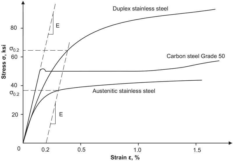
The primary difference in the structural behavior of stainless steel when compared to carbon steel is the shape of the stress-strain curve. As shown in Figure 1, typical carbon steels have a linear stress-strain relationship up to a definite yield point, after which stress no longer increases with strain. For stainless steel, the limit of proportionality, the point at which the stress-strain curve becomes non-linear, is very low, and the stress-strain curve has a rounded appearance, which results in a gradual reduction of stiffness as the stress increases. This stress-strain relationship generally affects limit states associated with local and global buckling, which are dependent on stiffness.
AISC 370 follows the same format as the Specification for Structural Steel Buildings (ANSI/AISC 360-16). The table of contents is almost identical, limit states are generally the same, and design methodologies are generally the same. Also, structural stainless steel can be designed using the same analysis methods as for carbon steel. Engineers accustomed to using AISC 360 to design carbon steel should find AISC 370 familiar. In most cases, the equations in AISC 370 are quite similar in format, although they may look slightly different, with different constants or coefficients.
One of the significant differences between carbon steel and stainless steel is not in the design of members but in the availability of sections. Wide flange, channels, angles, and round and rectangular hollow structural sections are all available in several stainless steel alloys. However, hot-rolled stainless steel sections are available only up to about eight inches. Beyond that, sections are built-up from plates with either fillet welds or laser-hybrid welds. This means one can specify a stainless steel W8x28 and receive a hot-rolled section with the same nominal dimensions and cross-section properties as a carbon steel section. However, if a stainless steel W16x31 is specified, the resulting section will have the same depth and flange width as a hot-rolled carbon steel section, but the flange thickness and web thickness will be slightly different. If one does not know if the desired section is available as hot-rolled, it should be assumed that the section will be built-up. AISC 313 requires that the cross-section of members be clearly defined in the design documents, including the overall dimensions and plate thicknesses of the components and joining requirements between elements of built-up sections. Therefore, it is best to work with fabricators and suppliers to ensure the desired sections are available.
Chapter B – Design Requirements
AISC 360 defines the design wall thickness for hollow structural sections (HSS) as 0.93 times the nominal wall thickness to account for tolerance on wall thickness for all materials except those produced to newer ASTM standards A1065 and A1085. AISC 370 is similar for HSS, with a slightly different coefficient, 0.95 times the nominal wall thickness. (The slight difference reflects how the tolerance on wall thickness is incorporated into the reliability factors.)
Due to tolerances in the ASTM standards for other types of stainless steel shapes and plates, AISC 370 also specifies the use of a design thickness equal to 0.95 times the nominal thickness for elements of sections that have a nominal thickness of less than or equal to 3⁄16 inches.
The width-thickness limits that categorize compact, non-compact, and slender elements define susceptibility to local buckling. In AISC 370, the width-thickness limits are more restrictive than those for carbon steel because, as noted above, the non-linear stress-strain curve of stainless steel affects conditions related to buckling. Also, sections are grouped differently in the tables for categorizing elements. For instance, the limits are the same for all flange-type elements, including hot-rolled wide flange sections, built-up I-shaped sections, channels, and angles. There are fewer groups because there is not enough data for stainless steel sections to justify adopting more tailored limits for specific types of cross-sections. Also, hot-rolled stainless steel I-shaped and channel sections are not abundant.
Chapter D – Design for Tension
The design of most structural stainless steel tension members is identical to the provisions of AISC 360. Due to the large ductility of stainless steel, especially austenitic alloys, the tensile strength may be associated with large deformations in the member. Therefore, a user note was added in AISC 370 to provide a means for calculating the maximum (average) stress in the net section based on a maximum allowable deformation. The maximum deformation depends on the project and is determined by the engineer.
Chapter E – Design for Compression
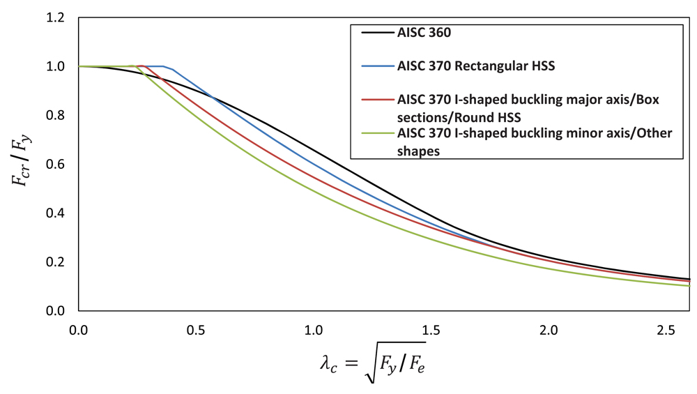
Buckling is a primary limit state for compression members, and as such, the design of compression members is affected by the non-linear stress-strain curve of stainless steel. At high slenderness (kL/r) values, column buckling is considered elastic and based on Euler buckling. Stresses in columns are generally low, and structural stainless steel columns perform about the same as corresponding carbon steel columns. At low slenderness, structural stainless steel columns can attain, and actually exceed, a yield load due to the beneficial property of strain hardening. (This is sometimes called the squash load, which is probably a better description because stainless steel experiences strain hardening that increases the strength as strain increases.) In the intermediate slenderness range, column buckling is in an inelastic range, and stainless steel columns have less capacity than corresponding carbon steel sections (Figure 2). By no means does this imply that stainless steel is not appropriate for columns.
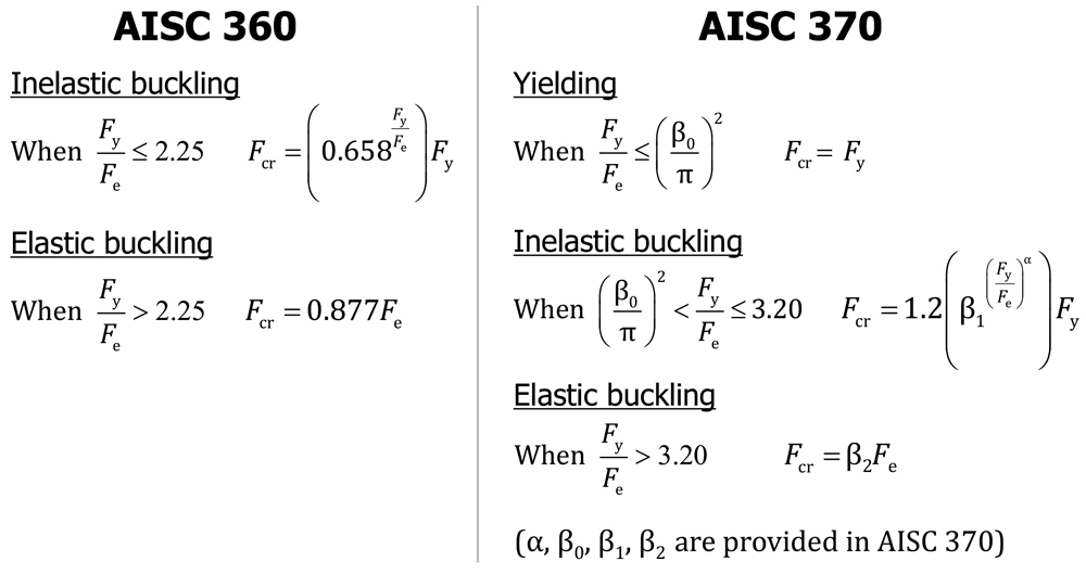
In AISC 370, there are separate column buckling curves for I-shaped sections buckling about their minor axis, for I-shaped sections buckling about their major axis and round HSS, and for rectangular HSS (Figure 3). Coefficients allow the use of a single set of equations for these three conditions.
Design for Flexure – Chapter F
The two main differences between AISC 360 and AISC 370 for flexural members are lateral torsional buckling (LTB) and local flange buckling. This is expected because the non-linear stress-strain curve for stainless steel affects limit states based on buckling.
For compact I-shaped members or channels (members with no local buckling of the web or flanges), AISC 360 has one buckling curve comprised of three parts. For an unbraced length less than Lp (the length at which yielding of the entire cross-section occurs, or the length for which LTB does not occur), LTB does not govern, and therefore the flexural strength of the beam is given by the plastic moment. For unbraced lengths larger than Lr (the maximum length at which inelastic LTB occurs), LTB is completely elastic. For carbon steel, Lr corresponds to 0.7My/Mp (Figure 4).
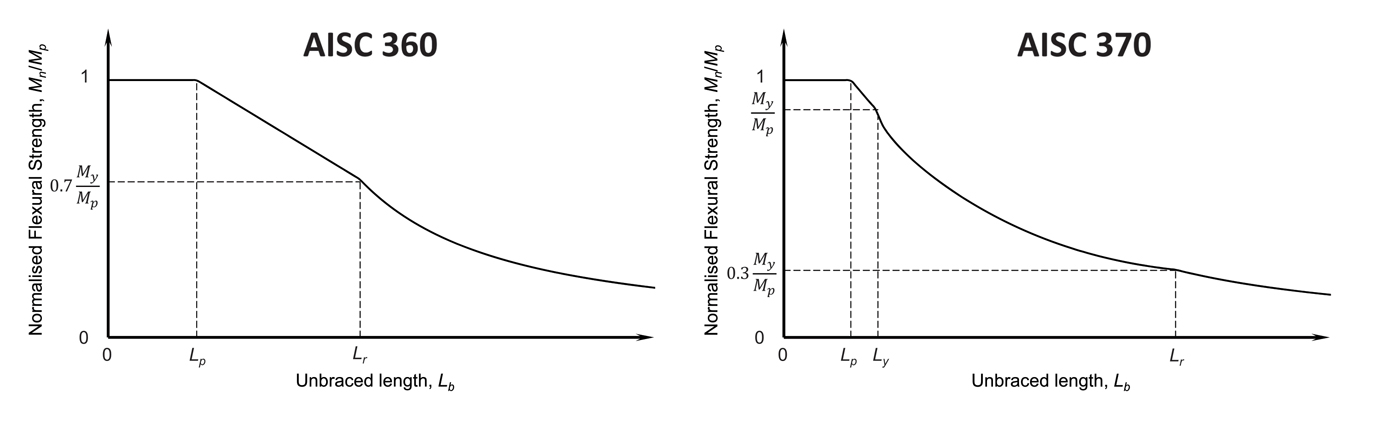
For stainless steel, AISC 370 has separate buckling curves for austenitic and duplex stainless steels, and each curve is composed of four parts. For an unbraced length less than Lp, the beam can reach the plastic moment, the same as for carbon steel. Then, the curve enters the inelastic region and decreases linearly to My at an unbraced length Ly. The second part of the inelastic LTB range goes from Ly to Lr. Notice that the inelastic region between Lp and Lr in AISC 360 for carbon steel is a straight line. This region is a curve in AISC 370 for stainless steel because of the non-linear stress-strain curve. For unbraced lengths larger than Lr, LTB is considered elastic, just like carbon steel. However, Lr corresponds to 0.3My/Mp for stainless steel, which moves Lr much farther out. The design will rarely be in this range.
For I-shaped sections and channels with non-compact webs, AISC 370 uses the same approach as AISC 360 with a web plastification factor. No standard carbon steel sections with Fy less than or equal to 70 ksi have non-compact webs. Similarly, there are no corresponding sections with non-compact webs in austenitic stainless steel. In duplex stainless steel, there are only about a dozen corresponding sections with non-compact webs. The equations in AISC 370 for LTB of sections with non-compact webs are quite similar to those in AISC 360, modified to reflect the differences in material properties and non-linear stress-strain curves.
Flange local buckling of slender flanges is one of only a few areas where the design methodology in AISC 370 differs from that in AISC 360. In AISC 360, the capacity is based on the elastic local buckling stress of the compression flange without consideration of post-buckling capacity. The flexural buckling strength is considered reached when the stress in the compression flange reaches the elastic local buckling stress. This approach is conservative because it does not account for the post-buckling strength. For this reason, it was decided to use the effective width method in AISC 370, where the effective width of the compression flange is used to calculate an effective section modulus.
Flange local buckling is only applicable for non-compact and slender flanges. In AISC 360, this applies to ten standard carbon steel sections. For austenitic stainless steels, there are only about three corresponding sections that would have non-compact flanges. Remember that very few hot-rolled standard sections are available in stainless steel. Flange local buckling needs to be considered for custom-built-up sections. For duplex stainless steel, as with higher-strength carbon steels, more corresponding sections have non-compact flanges because of the higher yield strength.
Chapter G – Design of Members for Shear and Torsion
Chapter G is the only place where the table of contents of AISC 370 differs from that of AISC 360. In AISC 360, torsion is in Chapter H with combined forces. Torsion was moved to Chapter G in AISC 370 because it is more of a shear consideration. The provisions for torsion are the same as in AISC 360 and include specific requirements for closed sections (round and rectangular HSS and box sections) subject to torsion. The Commentary for AISC 360 refers to AISC Design Guide 9 –Torsional Analysis of Structural Steel Members for open sections subject to torsion. Design Guide 9 can also be used for open stainless steel sections included in AISC 370. (It is best not to use open sections for torsion due to low torsional stiffness and large deformation.)
Generally, the provisions for shear in AISC 370 are the same as those in AISC 360, except the web shear strength coefficients are different to account for the non-linear stress-strain characteristics. For example, for sections other than round HSS or pipe, the web shear buckling coefficients, Cv1 or Cv2, can be as high as 1.2 to take advantage of stainless steel’s beneficial strain hardening characteristics. The expressions for the shear strength of round HSS differ from those for carbon steel, but they are based on the same design principles.
Chapter H – Design of Members for Combined Forces
Chapter H of AISC 370 is taken from AISC 360 without modification. The difference in the behavior of stainless steel members is already included in the strengths obtained from Chapters D, E, F, and G of AISC 370, so no change is necessary when combining the effects of different forces.
Summary
AISC 370 is a new design specification for hot-rolled, extruded, and welded stainless steel sections. It is adapted from AISC 360 and modified to reflect the difference in behavior between carbon steel and stainless steel. A few things from AISC 360 are not currently covered in AISC 370. However, it is not appropriate to use AISC 360 as a substitute for conditions not included in AISC 370. Work on AISC 370 is ongoing, and the next edition in 2027 should cover more situations.■